Method for detecting a leakage during operation of a braking system for a vehicle and braking system for a vehicle

a technology for braking systems and leakages, which is applied in the direction of instruments, vehicle sub-unit features, force/torque/work measurement apparatus, etc., can solve the problems of reducing the relief effect, and achieve the effect of facilitating the detection of leakages, reducing computing power, and advantageously shortening computing tim

Active Publication Date: 2020-02-13
ROBERT BOSCH GMBH
View PDF0 Cites 3 Cited by
  • Summary
  • Abstract
  • Description
  • Claims
  • Application Information

AI Technical Summary

Benefits of technology

[0022]According to one further specific embodiment of the method, it is provided that, during the pressure modulation, the actual braking pressure in the active circuit is set to a value greater than the setpoint braking pressure using a constant pressure gradient. Accordingly, it is possible to set the maximum actual braking pressure in a controlled manner. This facilitates the detection of a leakage, for example by carrying out the above-described chronological comparison.
[0023]According to one further specific embodiment of the method, it is provided that the piston speed is constant as the actual braking pressure is being lowered during the pressure modulation. In this way, the ascertainment of the volume flow generated by the piston during the pressure reduction is facilitated in terms of processing so that less computing power has to be provided on the hardware side, or the computing time is advantageously shortened for a given computing power.

Problems solved by technology

If a leakage occurs, the pressure reduction due to the leakage volume flow takes place considerably faster, thus reducing the relief effect.
On the other hand, a particularly high leakage volume flow typically occurs in these situations, so that it is easily and reliably detectable.

Method used


Image

  • Method for detecting a leakage during operation of a braking system for a vehicle and braking system for a vehicle
  • Method for detecting a leakage during operation of a braking system for a vehicle and braking system for a vehicle

Examples


Embodiment Construction

[0031]In the figures of the drawings, identical, functionally equivalent and identically acting elements, features and components are denoted by the same reference numerals, unless indicated otherwise.

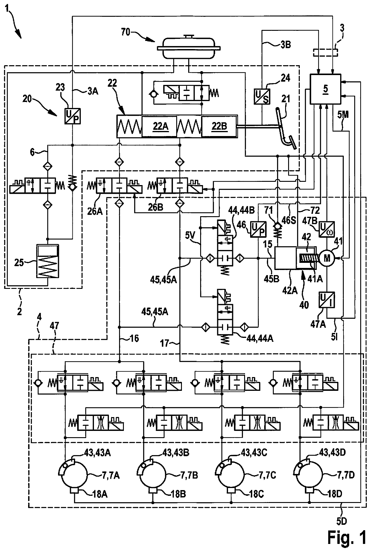
[0032]FIG. 1, by way of example, shows a braking system 1 for a vehicle. As is shown in FIG. 1, braking system 1 includes an actuating circuit 2, an active circuit 4, and a control unit 5.

[0033]Actuating circuit 2 shown by way of example in FIG. 1 includes a final control system 20 and an actuating unit 21. Final control system 20 may, in particular, as is shown by way of example in FIG. 1, include a hydraulic master brake cylinder 22 and a sensor unit having at least one pressure sensor 23 and one actuating distance sensor 24. Final control system 20 may furthermore include an optional return simulator 25. In final control system 20 shown by way of example in FIG. 1, master brake cylinder 22 is actuatable with the aid of actuating unit 21, which in FIG. 1 is shown as a foot pedal by w...


PUM


Abstract

A method is described for detecting a leakage during the operation of a braking system. A braking intention signal characterizing a braking intention is generated by actuating a final control system of an actuating circuit; a setpoint braking pressure required in an active circuit is ascertained based on the braking intention signal; an actual braking pressure in the active circuit is set according to the setpoint braking pressure with the aid of a pressure generation unit by moving a displacement piston to actuate a wheel brake coupled to the active circuit; and a pressure modulation is carried out. The pressure modulation includes setting the actual braking pressure in the active circuit to a value greater than the setpoint braking pressure, and lowering the actual braking pressure until the setpoint braking pressure is reached by moving the displacement piston at a predetermined piston speed. Furthermore, a chronological pressure gradient is ascertained, as the actual braking pressure is being lowered, during the pressure modulation, and a leakage of the active circuit is detected based on the ascertained pressure gradient when the pressure gradient is outside a range predetermined for the piston speed.

Description

BACKGROUND INFORMATION[0001]Braking systems for vehicles, in particular for motor vehicles, such as passenger cars or trucks, are usually implemented as electrohydraulic braking systems in which a hydraulic pressure is generated in a brake circuit for actuating wheel brakes by a master brake cylinder actuated with the aid of a manual actuating unit. The pressure generation in the braking force progression is usually supported by a pressure generation unit, which includes a movable displacement piston or plunger.[0002]So-called brake by wire systems are also increasingly used. Such a system is described in German Published Patent Application No. 10 2011 079 454, for example. In this braking system, an actuating circuit is provided, in which a hydraulic pressure is generated by actuating a master brake cylinder. This pressure is detected and, based on the detected pressure, a setpoint braking pressure is ascertained, which is set with the aid of a pressure generation unit, which inclu...

Claims


Application Information

Patent Timeline
Patent Type & Authority Applications(United States)
IPC IPC(8): B60T17/22B60T8/88
CPCB60T2270/403B60T8/885G01M3/26B60T17/221B60T13/66B60T17/22B60T7/042B60T13/146B60T13/662B60T13/686B60T13/745B60T8/171B60T8/172B60T13/741B60Y2200/11B60Y2200/145B60Y2400/30B60Y2400/81B60T8/4072B60T8/4081B60T8/409B60T17/18G01L5/28G01M3/00G01M3/02G01M3/025
Inventor FOITZIK, BERTRAMHAIBLE, TIMO
Owner ROBERT BOSCH GMBH
Why Eureka
Try Eureka