
Methods and systems for detecting and sealing dry fit connections in a piping assembly

a technology of piping assembly and dry fit connection, which is applied in the direction of pipe couplings, fluid tightness measurement, instruments, etc., can solve the problems of preferred joint assembly and fluid pressure that cannot be held by preferred joint assembly, and achieve the effect of facilitating leak detection

Inactive Publication Date: 2012-10-11
TYCO FIRE PRODS LP
View PDF2 Cites 7 Cited by
  • Summary
  • Abstract
  • Description
  • Claims
  • Application Information

AI Technical Summary

Benefits of technology

[0007]The present invention provides methods and systems for the assembly, construction and testing of piping systems that incorporates a joint connection or assembly capable of indicating an improper seal. Preferably, the joint assembly is configured for piping systems that employ socket-type fittings with a flowable sealant material to seal the joint assembly. In particular, the preferred joint assembly is unable to hold fluid pressure if the joint assembly is improperly sealed. In particular, the preferred joint assembly is unable to hold fluid pressure as a dry fit connection or as a partial seal. More specifically, the joint assembly includes a preferred coupler, i.e., a pipe fitting, a pipe end fitting or a modified pipe surface for joining piping segments, that includes a channel to form a leak path in cooperation with the pipe segment surface in an improperly sealed joint connection. Fluid can escape through the channel to identify to a piping system installer, contractor, owner or operator (collectively “operating personnel”) the improper seal, and in particular the absence of a sealant material to form the proper seal in the joint assembly. Accordingly, described herein are methods and systems for detecting and sealing dry fit connections in a piping assembly. Moreover, the inventors' couplers prevent the build up of fluid pressure around a dry fit joint connection absent any or a proper amount of sealant material. By eliminating the ability of a dry fit connection to hold fluid pressure, the connection cannot store potential energy and thus the potential for harm to the surrounding environment and personnel from a dry fit or partial seal connection is eliminated.
[0010]To facilitate leak detection, a preferred coupler is provided for forming a joint assembly in a fire protection piping system, the coupler includes a substantially tubular wall portion having an outer surface and an inner surface defining a passageway extending along an axis. The coupler further includes an end face extending between the inner surface and the outer surface to define a thickness of the tubular wall portion. A channel is disposed along one of the inner and outer surfaces and in communication with the passageway. The channel has a first configuration for carrying a fluid between an interior of the piping system and an exterior of a piping system. The channel has a second configuration to prevent fluid from being carried between the interior and the exterior of the piping system. The channel is further preferably convertible from the first configuration to the second configuration in the presence of a minimum amount of sealant material. Where the system has an initial internal pressure of about 10 psi of air, the channel in the first configuration provides for decrease in the system pressure at a preferred initial minimum rate of about 0.5 psi per minute. Under the hydraulic pressure testing at 10 psi, the channel configurations preferably provide an initial minimum rate of pressure change of 0.5 psi / 2 min.

Problems solved by technology

In particular, the preferred joint assembly is unable to hold fluid pressure if the joint assembly is improperly sealed.
In particular, the preferred joint assembly is unable to hold fluid pressure as a dry fit connection or as a partial seal.
Moreover, the inventors' couplers prevent the build up of fluid pressure around a dry fit joint connection absent any or a proper amount of sealant material.

Method used


Image

  • Methods and systems for detecting and sealing dry fit connections in a piping assembly
  • Methods and systems for detecting and sealing dry fit connections in a piping assembly
  • Methods and systems for detecting and sealing dry fit connections in a piping assembly

Examples


Embodiment Construction

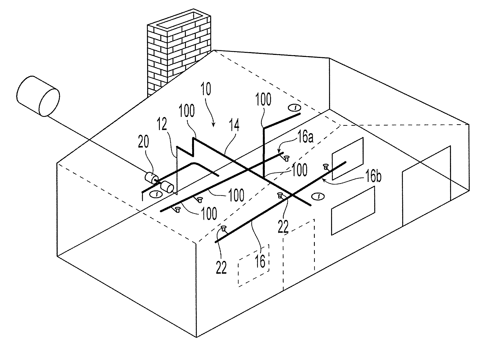
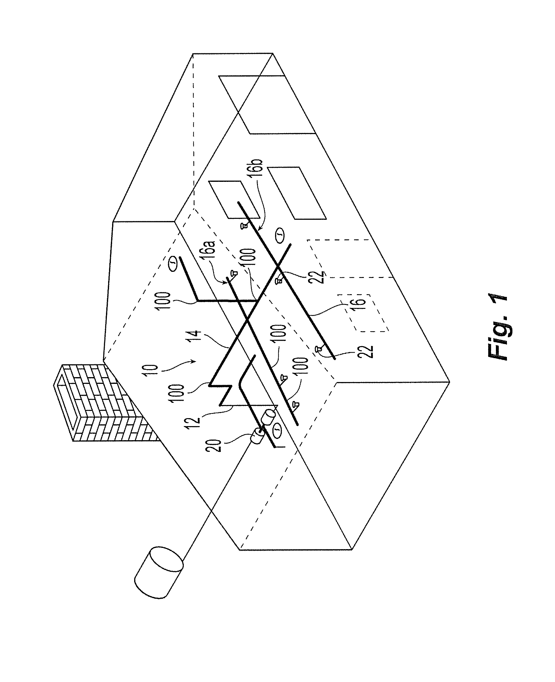
[0029]Shown in FIG. 1 is an illustrative embodiment of a preferred piping system 10 for carrying a fluid as either a gas, a liquid or a combination thereof. More specifically shown is a preferred piping network 10 for a fire protection system. The system 10 is preferably constructed from Post Chlorinated Polyvinyl Chloride (CPVC) piping segments and fittings such as for example, Tyco Fire & Building Products TFP Blazemaster® piping systems as shown and described in the “Blazemaster®: Installation Instructions & Technical Handbook” (Rev. 0 Jan. 2005) (Addendum #1 / IH-1900 (October 2005)), each of which is incorporated in its entirety by reference. The system 10 includes a network of piping elements, which can include any one of: main lines 12, branch lines 14, sprigs, drops, risers 16, pipe nipples 18, valves 20, sprinklers and / or nozzles 22, and alarm devices. To interconnect and join the various pipe elements, the system 10 preferably includes one or more joint connections or assemb...


PUM


Abstract

Systems and methods for evaluating a piping system for an improperly assembled fluid tight connection. Provided is a preferred joint assembly unable to hold fluid pressure in either one of a dry fit connection and partial seal connection. The joint assembly includes a coupler to identify a leak. More specifically, the coupler includes a substantially tubular wall portion having an outer surface, an inner surface and a channel disposed along one of the inner and outer surfaces. The channel has a first configuration for carrying a fluid between an interior of the piping system and an exterior of a piping system, and a second configuration to prevent fluid from being carried between the interior and the exterior of the piping system. The channel is further preferably convertible from the first configuration to the second configuration in the presence of a minimum amount of sealant material.

Description

PRIORITY DATA & INCORPORATION BY REFERENCE[0001]This is a National Stage application under 35 U.S.C. 371 of International Application No. PCT / US2008 / 050821, filed Jan. 10, 2008 which claims the benefit of priority to (i) U.S. Provisional Patent Application No. 60 / 977,010 filed Oct. 2, 2007; (ii) U.S. Provisional Patent Application No. 60 / 956,655 filed Aug. 17, 2007; (iii) U.S. Provisional Patent Application No. 60 / 917,459 filed May 11, 2007; and (iv) U.S. Provisional Patent Application No. 60 / 884,262 filed Jan. 10, 2007, each of which is incorporated by reference in its entirety.TECHNICAL FIELD[0002]The present invention relates to methods and systems for verifying and ensuring the integrity of a piping system that uses a sealant material in its joint assemblies to form fluid tight sealed joint connections or assemblies. More specifically, the methods and systems are provided for detecting a joint connection in the system without a sealant material (a dry fit connection), or a joint...

Claims


Application Information

Patent Timeline
Patent Type & Authority Applications(United States)
IPC IPC(8): G01M3/08
CPCG01M3/2853F16L2201/30F16L21/02F16L21/06F16L55/00F16L55/16
Inventor GOLINVEAUX, JAMES E.SCHIAVONE, CARMINE L.AMARELLO, JOHN A.
Owner TYCO FIRE PRODS LP
Learn More