Surgical drape and panel assembly

a surgical drape and panel technology, applied in the field of surgical drapes, can solve the problems of cotton-based surgical drapes that were flawed, bacteria on the skin of patients and/or unsterilized equipment may infect the surgical site, and the risk of infection, so as to improve the surgical field and reduce the amount of foreign tubing used

Inactive Publication Date: 2006-08-31
MAQUET CARDIOVASCULAR LLC
View PDF6 Cites 9 Cited by
  • Summary
  • Abstract
  • Description
  • Claims
  • Application Information

AI Technical Summary

Benefits of technology

[0016] By utilizing the present invention, the surgeon may place the sterile pump closer to the surgical site, thereby reducing the amount of foreign tubing that is necessary to connect the blood pump to the cannulas placed within the patient's vascular system. A further advantage of the invention is that the pump, driving mechanism, and control panel may be located at a distance closer to the surgeon, thereby enabling the surgeon to view the information more readily. The driving mechanism and control panel may be located near the patient's head, thereby allowing the perfusionist closer monitoring of the pump system and the patient's vital signs.
[0017] In one embodiment of the present invention, the surgical drape is designed such that it is to be disposed adjacent to the patient's head region. The surgical drape is sufficiently thin so as to allow the surgeon to couple a sterile blood pump to a non-sterile driving mechanism without interfering with the clamping mechanism.
[0018] In another embodiment the surgical drape further contains apertures which allow sterile materials to be passed through from the surgical site, to the non-sterile surgical site adjacent to the patient's head area. Thereby allowing a sterile pump to be placed closer to the surgical site while the non-sterile driving mechanism is placed outside the sterile surgical field. Thus further reducing the amount of foreign tubing used to connect the blood pump to the patient's vascular system.
[0019] In another embodiment, the surgical drape further comprises a rigid panel disposed about the head / neck region of the patient, whereby the panel is adapted to receive a blood pump and associate tubing during a surgical procedure.
[0020] In another embodiment the surgical drape of the present invention further comprises a clear viewing portion thereby allowing the surgeon / anesthesiologist look through the drape instead of having to move around the drape.
[0021] In another embodiment, the rigid panel structure further contains connectors for various medical devices utilized during a surgical procedure. Thus, by utilizing the panel and the connections contained thereon the surgeon is better able to organize the surgical field.

Problems solved by technology

The need for surgical drapes stems from the inherent risk for infection during surgical procedures.
More specifically, bacteria on the patient's skin and / or from unsterilized equipment may infect the surgical site.
However, bacteria may nonetheless pass through the fibers forming the cotton drape, and fibers may become detached from the drape, presenting the possibility for bacteria to enter the operative site.
While an improvement, these newer cotton-based surgical drapes were nonetheless flawed in that the finish loses its liquid repellant characteristics over time.
Another drawback to cotton-based surgical drapes is that they are predisposed to produce lint, which thereby provides a transport medium for the bacteria.
This additional medical tubing increases the priming volume of the CPB circuit and may also increase hemolysis based on the exposure to a greater amount of foreign surface area, i.e. the tubing.
The surgeon is typically unable to view the pump or control panel at any time during the procedure.
The CPB circuit described above, while very common in use, is nonetheless flawed in several significant ways.
First, this prior art CPB circuit is undesirable because it increases the amount of foreign material that the blood is in contact with, thereby increasing the likelihood of hemolysis.
Another significant drawback of the CPB system of the prior art is that the surgical field (due to the inability to sterilize the motor).
This disadvantageously clutters the operating room.
Moreover, the information displayed on the CPB equipment must be relayed to the surgeon, thereby further complicating the procedure.

Method used


Image

  • Surgical drape and panel assembly
  • Surgical drape and panel assembly
  • Surgical drape and panel assembly

Examples


Embodiment Construction

[0033] Illustrative embodiments of the invention are described below. In the interest of clarity, not all features of an actual implementation are described in this specification. It will of course be appreciated that in the development of any such actual embodiment, numerous implementation-specific decisions must be made to achieve the developers' specific goals, such as compliance with system-related and business-related constraints, which will vary from on implementation to another. Moveover, it will be appreciated that such a development effort might be complex and time-consuming, but would nevertheless be a routine undertaking for those of ordinary skill in the art having the benefit of this disclosure.

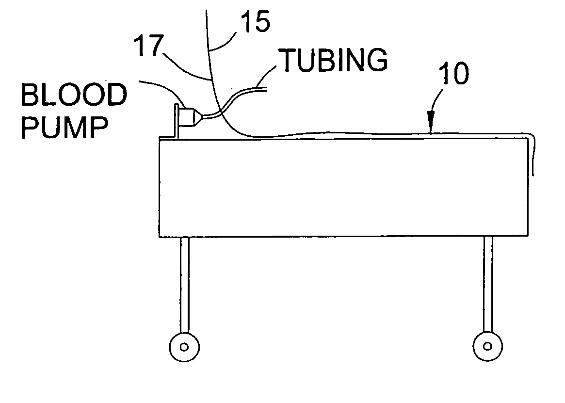
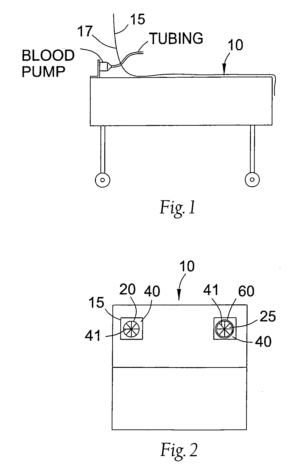
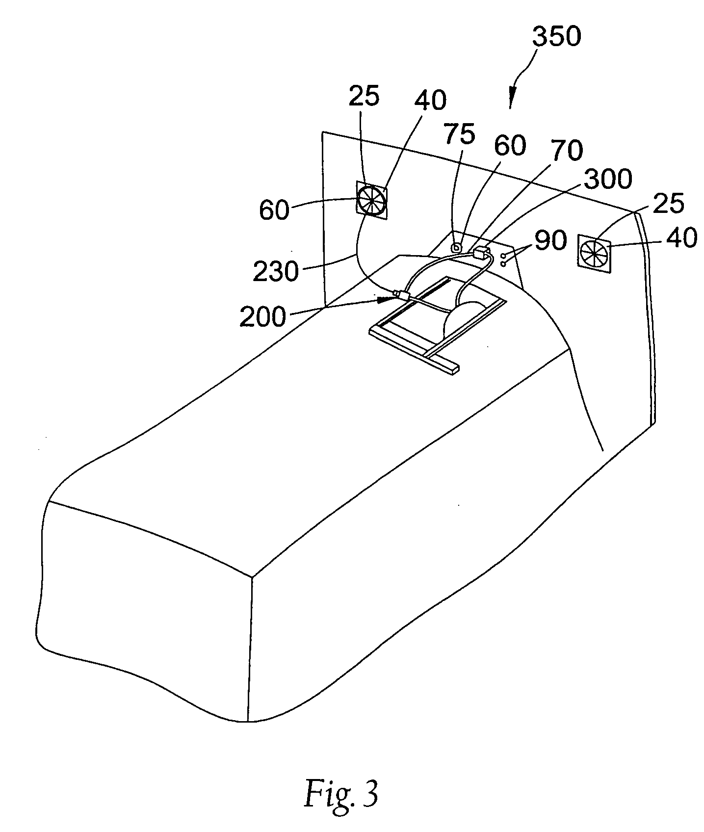
[0034] Referring now to the drawings, there is shown a preferred embodiment of a surgical drape in accordance with the present invention. The drape is particularly suited for use during cardiovascular procedures where a blood pump is utilized or for any other surgical procedures...


PUM


Abstract

A disposable surgical drape for use in cardiovascular surgical procedures which may optionally be used to isolate a sterile pumping mechanism from a non-sterile pump driving mechanism and / or provide support for medical equipment, such as medical tubing.

Description

RELATED APPLICATIONS [0001] This application is a continuation of co-pending U.S. patent application Ser. No. 11 / 058,621 filed 15 Feb. 2005, which is a continuation of abandoned U.S. patent application Ser. No. 10 / 445,639 filed 27 May 2003, which is a continuation of abandoned U.S. patent application Ser. No. 09 / 729,740 filed 4 Dec. 2000, which claims the benefit under Title 35, United States Code, §110(e) of U.S. Provisional Application No. 60 / 168,795 filed on Dec. 2, 1999 and entitled “Surgical Drape and Panel Assembly.”BACKGROUND OF THE INVENTION [0002] I. Field of the Invention [0003] The present invention relates generally to surgical drapes. More particularly, the present invention relates to a disposable surgical drape for use in cardiovascular surgical procedures which advantageously maintains sterile and clean conditions at an operation site and may optionally be used to isolate a sterile pumping mechanism from a non-sterile pump driving mechanism and / or provide support for...

Claims


Application Information

Patent Timeline
Patent Type & Authority Applications(United States)
IPC IPC(8): A61B19/00A61B19/08A61F5/37A61B46/23
CPCA61B19/08A61B19/081A61B19/088A61B19/10A61B2019/103A61B46/23A61B2046/234A61B46/00A61B46/10A61B46/40
Inventor ABOUL-HOSN, WALID NALIBYOUMANS, SCOTT
Owner MAQUET CARDIOVASCULAR LLC
Why Eureka
Try Eureka