Production method of discharge lamp

Inactive Publication Date: 2006-08-31
PANASONIC CORP
View PDF8 Cites 8 Cited by
  • Summary
  • Abstract
  • Description
  • Claims
  • Application Information

AI Technical Summary

Benefits of technology

[0006] The present invention aims to provide a discharge lamp manufacturing method that enables the energy loss of laser irradiation from the second time onward

Problems solved by technology

However, due to the inventors' investigations aimed mainly at the large-scale production of such discharge lamps, it was revealed that energy loss from the laser beam occurs when the laser beam is irradiated a second time from outside the arc tube to melt the tips of the electrodes after the initial laser irradiation to fusion cut the cutting site, thus resulting in a drop in efficiency when usin

Method used


Image

  • Production method of discharge lamp
  • Production method of discharge lamp
  • Production method of discharge lamp

Examples


Embodiment Construction

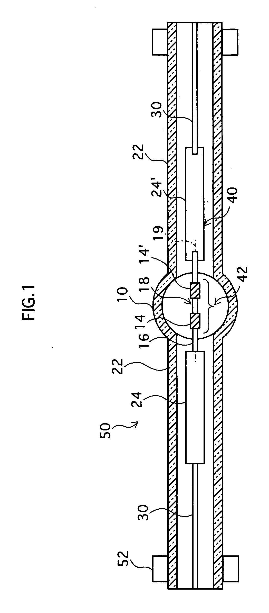
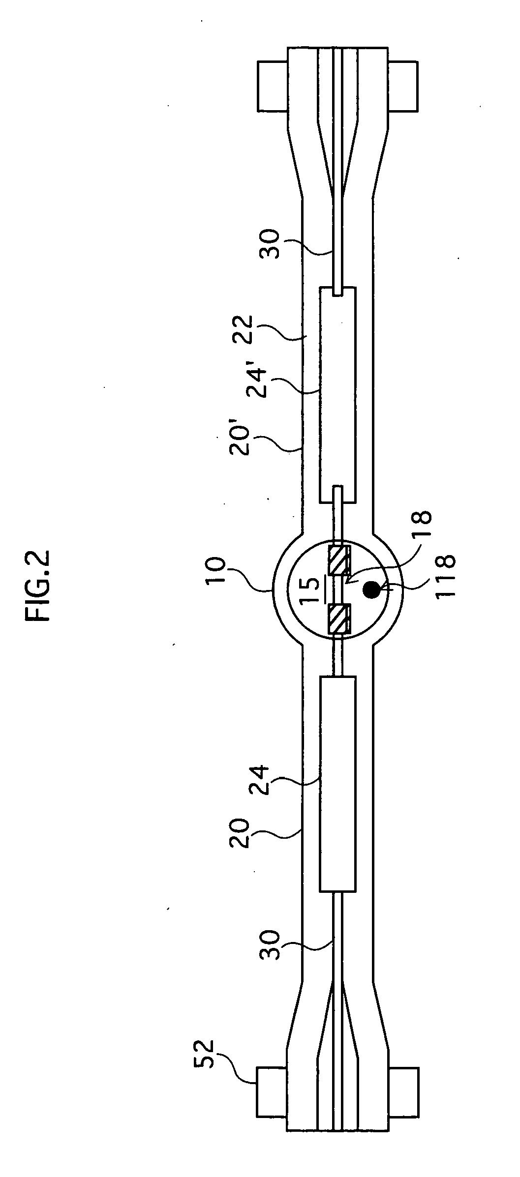
[0021] A preferred embodiment of a discharge lamp manufacturing method pertaining to the present invention is described below while referring to the drawings. FIGS. 1 to 3 illustrate a manufacturing method for a high-pressure mercury lamp as an exemplary discharge lamp manufacturing method pertaining to the preferred embodiment of the present invention.

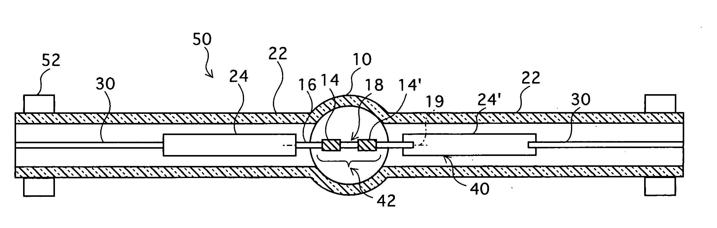
[0022] With this embodiment, as shown in FIG. 1, a glass bulb 50 for use in a discharge lamp and a single electrode assembly 40 that includes an electrode structural portion 42 for forming a pair of electrodes in the discharge lamp are firstly prepared, after which electrode assembly 40 is inserted into glass bulb 50.

[0023] Glass bulb 50 has a substantially spherical arc-tube part 10 for forming an arc tube of a discharge lamp, and side-tube parts 22 extending from arc-tube part 10. A section of each side-tube part 22 is for forming a sealing part of a discharge lamp. Glass bulb 50 may be held in place by chucks 52, for example. In ...


PUM


Abstract

A discharge lamp manufacturing method that enables the energy loss of a laser beam irradiated from outside an arc tube to be suppressed when forming a pair of electrodes by fusion cutting a predetermined cutting site of a tungsten rod disposed within a sealed arc space. Even when a film of an arc material (e.g., mercury) forms on an inner wall of an arc tube (10) due to the arc material evaporating when the temperature of the arc tube (10) is raised as a result of a laser beam (60) being irradiated from outside the arc tube (10), this manufacturing method is able to eliminate the film through evaporation by heating the arc tube (10) with a coil heater (125) before irradiating the laser beam (60) again.

Description

TECHNICAL FIELD [0001] The present invention relates to a manufacturing method for discharge lamps, and in particular to a manufacturing method for a short-arc discharge lamp whose interelectrode distance has been shortened to move the electrodes closer to the point light source. BACKGROUND ART [0002] In recent years much research and development has gone into various types of projectors for realizing image display on large screens such as LCD (liquid crystal display) projectors and projectors using a DMD (digital micromirror device). Discharge lamps such as short-arc, high-pressure mercury lamps whose interelectrode distance has been reduced to 1.0 mm or less, for example, to move the electrodes closer to the point light source have been attracting attention as a possible light source for such projectors. [0003] A manufacturing method for such discharge lamps disclosed, for example, in Japanese Patent No. 3,330,592 and Japanese Patent Application Publication No. 7-45237 involves in...

Claims


Application Information

Patent Timeline
IPC IPC(8): H01J61/36H01J9/00H01J9/04H01J61/073H01J61/86
CPCH01J9/042H01J61/0732H01J61/86
Inventor OGINO, YUICHIROMINO, YOSHIMITSUKIKUCHI, AKIOUENO, HIRONOBUMURASE, TALAYUKI
Owner PANASONIC CORP
Why Eureka
Try Eureka