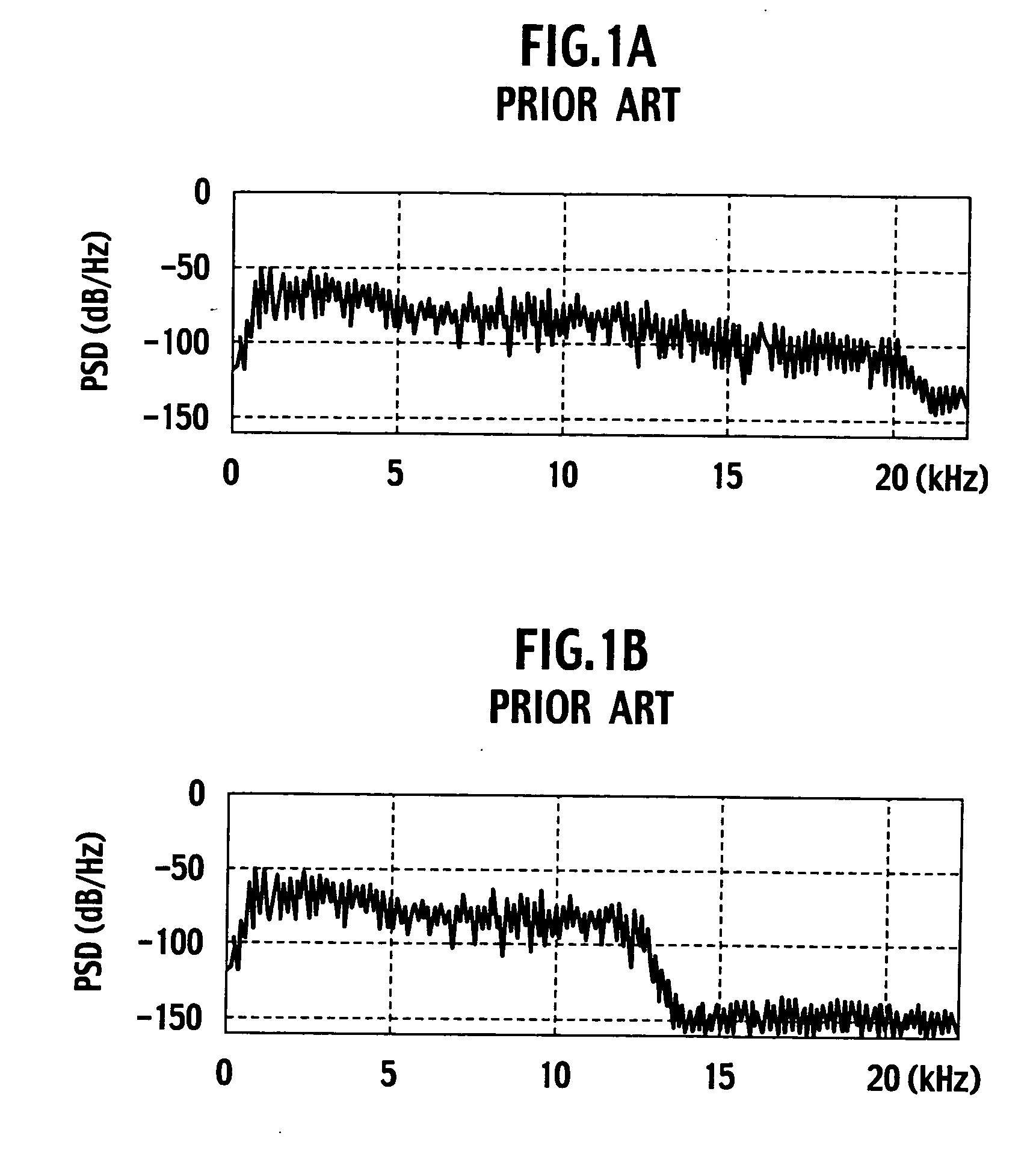
High frequency compensator and reproducing device
a high frequency compensator and reproducing device technology, applied in the field of high frequency compensators and reproducing devices, can solve the problems of low compression rate, information loss, and sound quality deterioration, and achieve the effect of reducing the cost of production, and improving the quality of production
- Summary
- Abstract
- Description
- Claims
- Application Information
AI Technical Summary
Benefits of technology
Problems solved by technology
Method used
Image
Examples
first embodiment
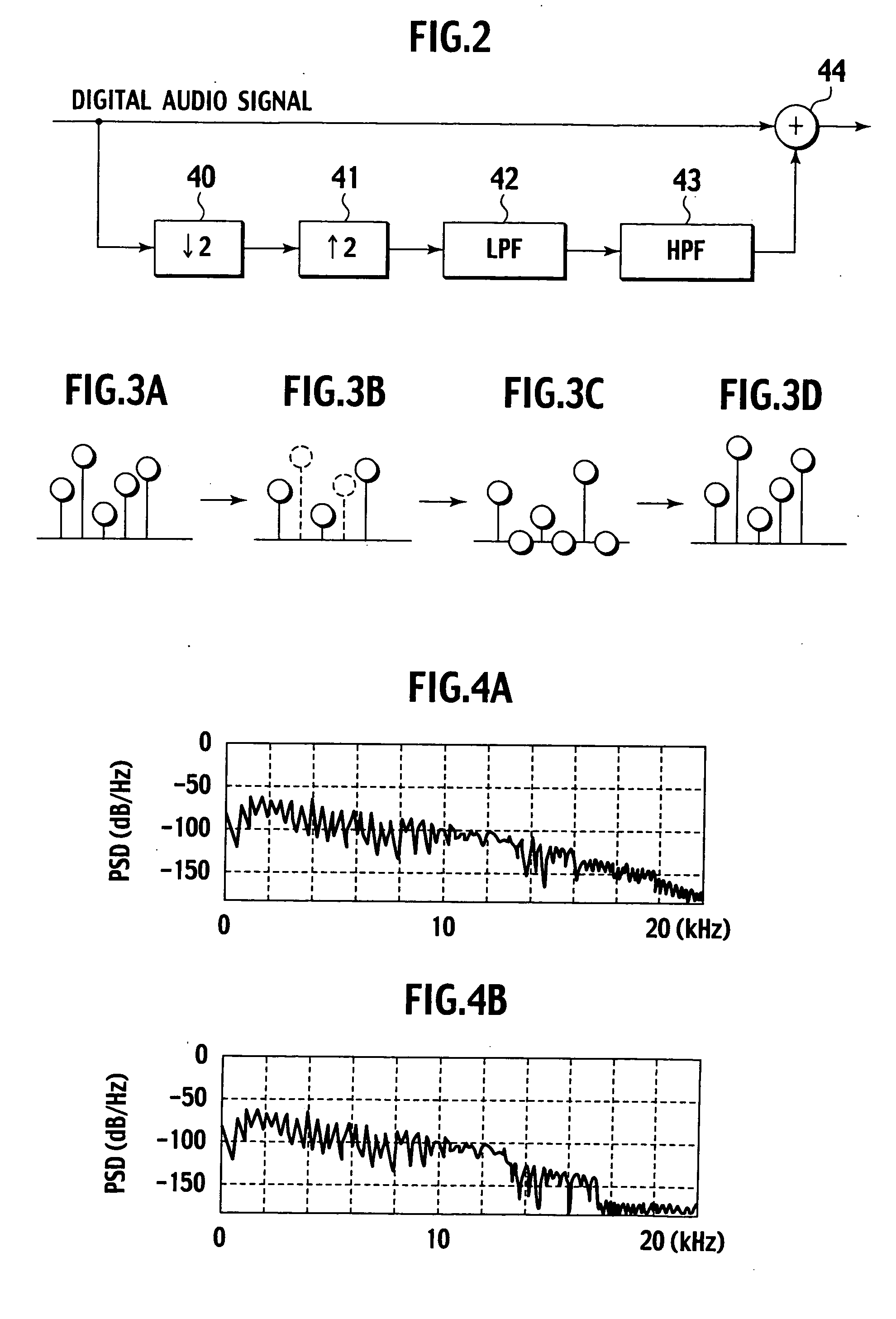
[0025]FIG. 2 is a block diagram showing a schematic configuration of a high frequency compensator according to a first embodiment of the present invention. In the high frequency compensator according to the first embodiment, a down sampler 40 performs ½ down-sampling of a compressed and expanded digital audio signal as shown in FIG. 3A, and a sampling value is decimated as shown in FIG. 3B. The digital audio signal subjected to the ½ down-sampling is supplied to an up sampler 41.
[0026] The up sampler 41 performs double up-sampling for the supplied digital audio signal, and inserts a sampling point with sampling value “0” at the midpoint of each sampling value (zero insertion). The digital audio signal having undergone the double up-sampling generates an axisymmetric spectrum (imaging component) with respect to its axis of symmetry, for example, 11 kHz (when the original sampling frequency is 44.1 kHz).
[0027] The digital audio signal having undergone the double up-sampling by the u...
second embodiment
[0040]FIG. 6 is a block diagram showing a configuration of an optical disk device as a reproducing device according to a second embodiment of the present invention. The optical disk device is a mini disk device capable of recording and reproducing. A cartridge 12, which stores a mini disk 11 therein, with a square planar shape is loaded on the mini disk device. In this sate, shutters on both sides of the cartridge 12 are opened, and an optical pickup 15 carries out reading from one side of the mini disk 11 through an object lens 14. At the time of recording, magnetic field is applied to the other side of the mini disk 11 by a magnetic head 19.
[0041] The mini disk 11 is driven to rotate by a spindle motor 13 so as to have a predetermined constant linear velocity. The optical pickup 15 is driven by a motor 16 and moves in a radial direction of the mini disk 11. The magnetic head 19 is driven by a head driver 20 at the time of recording and moves in a radial direction of the mini disk...
PUM
 Abstract
Description
Claims
Application Information
 - R&D
- Intellectual Property
- Life Sciences
- Materials
- Tech Scout
- Unparalleled Data Quality
- Higher Quality Content
- 60% Fewer Hallucinations
Browse by: Latest US Patents, China's latest patents, Technical Efficacy Thesaurus, Application Domain, Technology Topic, Popular Technical Reports.
© 2025 PatSnap. All rights reserved.Legal|Privacy policy|Modern Slavery Act Transparency Statement|Sitemap|About US| Contact US: help@patsnap.com


