Supercharge Your Innovation With Domain-Expert AI Agents!

Image forming apparatus

a technology of forming apparatus and supporting member, which is applied in the direction of printing, instruments, optics, etc., can solve the problems of unevenness or warpage of images, deterioration of image quality, and possible gap between the supporting member and the unit chassis at the supporting member in one place, so as to prevent vibration propagation, particularly effective effect of resonance prevention

Inactive Publication Date: 2006-08-31
KYOCERA DOCUMENT SOLUTIONS INC
View PDF2 Cites 1 Cited by
  • Summary
  • Abstract
  • Description
  • Claims
  • Application Information

AI Technical Summary

Benefits of technology

[0015] With the above structure, the reinforcing area hardly warps even when completely fixed by three of the main fixing members, and the optical instruments mounted therein can therefore be positioned with high accuracy.
[0017] As described in the above, in the unit chassis forming nearly a cube in general, the percentage of the free part with weak restrained condition of displacement can be lowered by fixedly supporting in four or more places, and therefore, the resonance with the driving members of the polygon mirrors or peripheral devices mounted in the unit chassis can be prevented.
[0023] With the above structure, the vibration propagation from the vibration source (light scanning means) can be effectively deadened.
[0024] Additionally, when the light scanning means and the reflecting mirror that reflects the beam light scanned by the light scanning means across its scanning range are provided as the structural element of the optical instruments, the reflecting mirror is easily influenced particularly from the vibration propagated from the light scanning means among the optical instruments, since having a long and thin figure.
[0026] With the structure noted above, the high-reinforcing area between two of the main fixing members hardly vibrates, and moreover, the propagation of the vibration from the light scanning means can be intercepted by the high-reinforcing area, thereby preventing the vibration propagated to the vibration-sensitive reflecting mirror.
[0028] Moreover, it is particularly effective for resonance prevention when the light scanning means as the vibration source is mounted in the position or in vicinity thereof inside of a triangle formed by three of said main fixing members, and alternatively, when ribs are extendedly formed along the emitting direction from the light scanning means (vibration source), in other words, along the direction of vibration propagation or the close direction thereof (direction intersecting at a sharp angle) in the area close to the mounting position of the light scanning means (vibration source) outside of the triangle in the reinforcing areas.

Problems solved by technology

Here, the deterioration of image quality, such as unevenness or warps of the image, might occur when the accuracy of irradiation position of the beam light onto the photoreceptor drum is low.
In this case, the gap between the supporting member and the unit chassis at the supporting member in one place may occur caused by, such as unevenness of the heights of supporting members in the side of the main body in four places and fluctuation in the shape of the unit chassis.
This causes the warps of the unit chassis, thereby deteriorating the positioning accuracy of the optical instruments mounted therein.
When the percentage of this free part becomes large, it easily resonates with vibration of the driving members of, such as polygon mirrors and peripheral devices mounted in the unit chassis, and therefore, with such resonance, deterioration of the positioning accuracy of the optical instruments has been occurred.

Method used


Image

  • Image forming apparatus
  • Image forming apparatus
  • Image forming apparatus

Examples


Embodiment Construction

[0036] With embodiments of the present invention described hereinafter with reference to the accompanying drawings, it is to be understood that the invention is not limited to those precise embodiments, and that various changes and modifications may be effected therein by one skilled in the art without departing from the scope or spirit of the invention as defined in the appended claims.

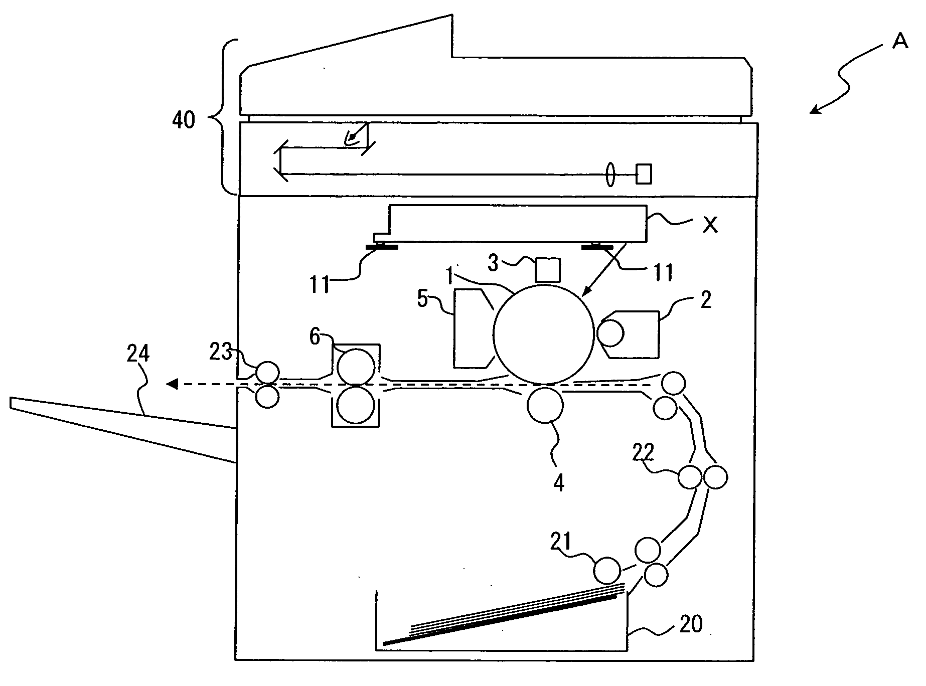
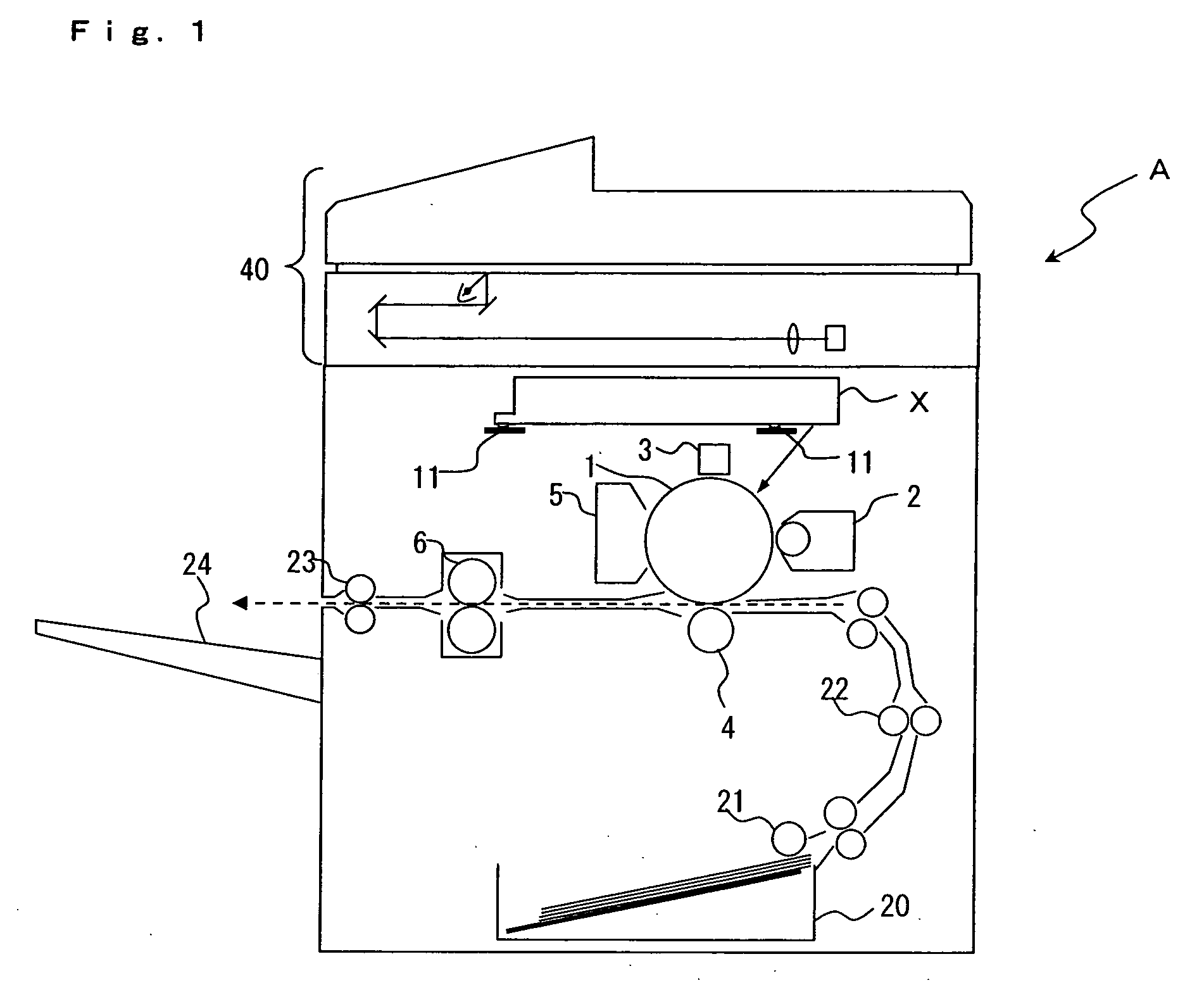
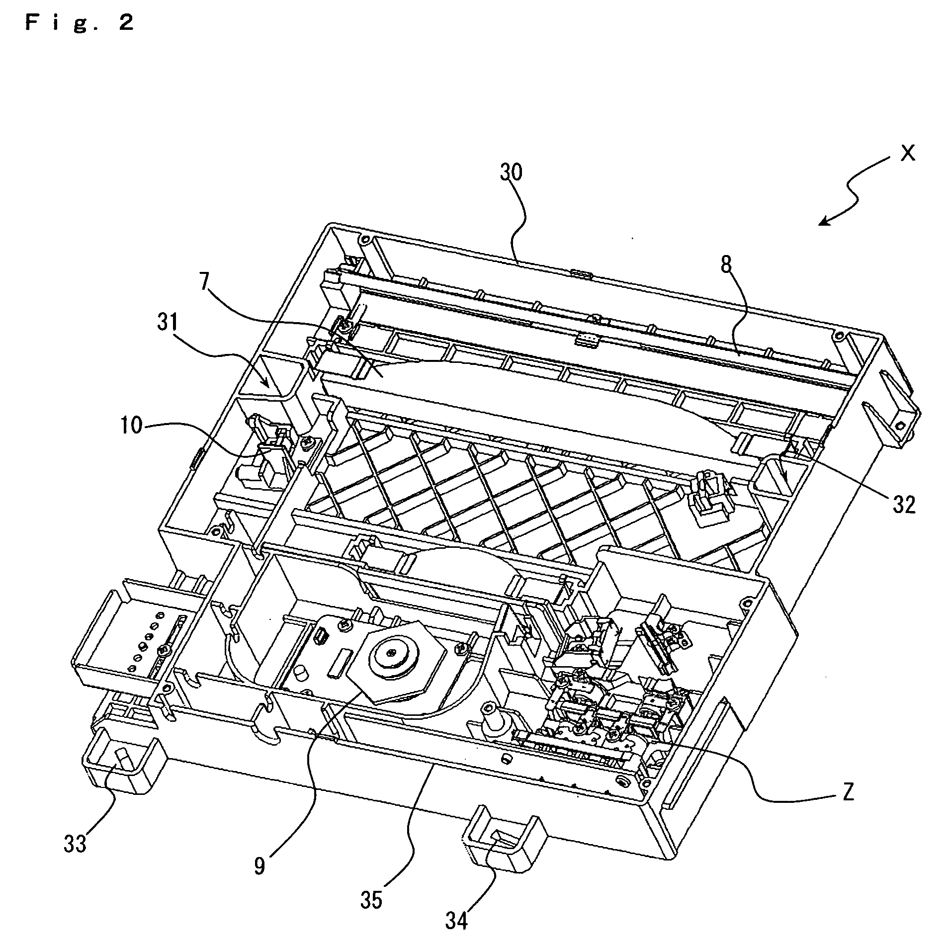
[0037] Image forming apparatus A according to an embodiment of the present invention is comprised of a unit chassis as a solidly shaped member in which the optical instruments for image formation are mounted. The unit chassis are provided with three of main fixing members formed in reinforced reinforcing areas or in the contiguous areas thereof, as well as one or more of subsidiary fixing member connected to the main fixing members by a flexible member. These fixing members and the subsidiary member are provided in the positions forming a polygon. This arrangement is one of the characteristics of Im...


PUM


Abstract

This invention provides a image forming apparatus, which combines the prevention of warp and the prevention of resonance of the unit chassis in which the optical instruments for image formation are mounted, neither with additional parts nor additional mounting processes thereof. For example, in Unit chassis 30 in which optical instruments are mounted, three of Main fixing members 31, 32 and 33 formed in the reinforced reinforcing areas or in the contiguous areas thereof, as well as Subsidiary fixing member 34 connected to said main fixing members by Flexible member 35, are provided, and Unit chassis 30 is fixed by said fixing members in more than four places. The polygon mirror as a vibration source is mounted in the position 9x that are inside of a triangle PO formed by three of Main fixing members 31, 32 and 33 or in the vicinity thereof. In this case, high-reinforcing area P2 reinforced more than any other area is formed between said position 9x and the position 8x of deflecting mirror for reflecting the scanned beam light. Main fixing members 31 and 32 among three of Main fixing members are formed in two places having the high-reinforcing area between them.

Description

BACKGROUND OF THE INVENTION [0001] 1. Field of the Invention [0002] The present invention relates to an image forming apparatus comprising an optical unit that consists of optical instruments for image formation mounted in a solidly shaped chassis. [0003] 2. Description of the Related Art [0004] The image forming apparatuses of electrophotographic system (such as copy machines, printers, and facsimiles) generally write an electrostatic latent image by scanning the beam light on the surface of the electrically-charged photoreceptor, or by exposing the surface of the photoreceptor by means of LED array light source that is arranged in the direction of the rotational axis of the drum-shaped photoreceptor. The beam light is emitted from the light source, such as a laser diode, then scanned in the prescribed main scanning direction by a light scanning apparatus that comprises optical instruments, such as one or a plurality of reflecting mirrors (deflecting mirror), lenses (such as fθ len...

Claims


Application Information

Patent Timeline
IPC IPC(8): B41J2/385
CPCB41J2/471B41J29/02
Inventor OHNISHI, MASATO
Owner KYOCERA DOCUMENT SOLUTIONS INC
Features
  • R&D
  • Intellectual Property
  • Life Sciences
  • Materials
  • Tech Scout
  • Unparalleled Data Quality
  • Higher Quality Content
  • 60% Fewer Hallucinations
Learn More