Gas sensors

a technology of gas sensors and sensors, applied in the field of gas sensors, can solve the problems of increased response time, corresponding loss of responsiveness to changing signal levels, and inability to detect the output signal of diffusive photoacoustic sensors, so as to reduce external noise and adequate response time

Inactive Publication Date: 2006-08-31
MINE SAFETY APPLIANCES CO +1
View PDF5 Cites 7 Cited by
  • Summary
  • Abstract
  • Description
  • Claims
  • Application Information

AI Technical Summary

Benefits of technology

[0005] In one aspect, the present invention provides a sound / pressure damping element (SDE) designed for use in a diffusive, non-resonant photoacoustic gas sensor (detector). The SDE reduces external, low-frequency noise to acceptable levels while permitting the photoacoustic detector (sensor) to maintain an adequate response time to changing gas concentration levels.
[0008] Preferably, the second volume is larger than the first volume to enhance attenuation of external pressure fluctuations. The first volume may, for example, be connected to the second volume by a channel that is shaped to limit diffusion of analyte gas therethrough. The channel may, for example, be elongated and of small cross section compared to the opening into the first volume.
[0010] In another aspect, the present invention provides a photoacoustic detector including a measuring system to measure the photoacoustic excitation of analyte gas entering the photoacoustic detector, a reference system to measure the effect of pressure waves in the environment, and a system for offsetting an output from the measuring system with an output from the reference system to reduce noise resulting from pressure waves in the environment in an output signal of the photoacoustic detector. The measuring system can, for example, include a first microphone to measure photoacoustic excitation of gas; and the reference system can include a second microphone to measure an offset signal that is processed by the system electronics to reduce the effect of externally generated pressure waves on the output signal of the photoacoustic sensor. The reference system can, for example, be disposed within an SDE volume as described above. The first microphone can also be disposed within a photoacoustic cell, and the second microphone can be disposed within a reference cell. The photoacoustic cell and the reference cell are preferably well matched (for example, of generally the same volume).
[0011] In a further aspect, the present invention provides a photoacoustic detector including a measuring cell, a reference cell and a pressure gradient microphone coupled between the two cells. The pressure gradient microphone measures the pressure difference between the measurement cell and the reference cell to reduce noise from external pressure waves in an output of the photoacoustic sensor.

Problems solved by technology

However, the output signal of a diffusive photoacoustic sensor is susceptible to noise created by interference from outside sources of air pressure fluctuations, such as wind, vibration and acoustic phenomena.
However, one must balance this attenuating effect with an increase in response time.
In that regard, introduction of a sound / pressure attenuating element(s) to reduce noise typically results in a corresponding loss of responsiveness to changing signal levels.

Method used


Image

  • Gas sensors
  • Gas sensors
  • Gas sensors

Examples


Embodiment Construction

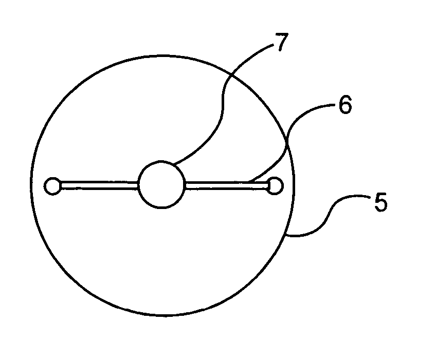
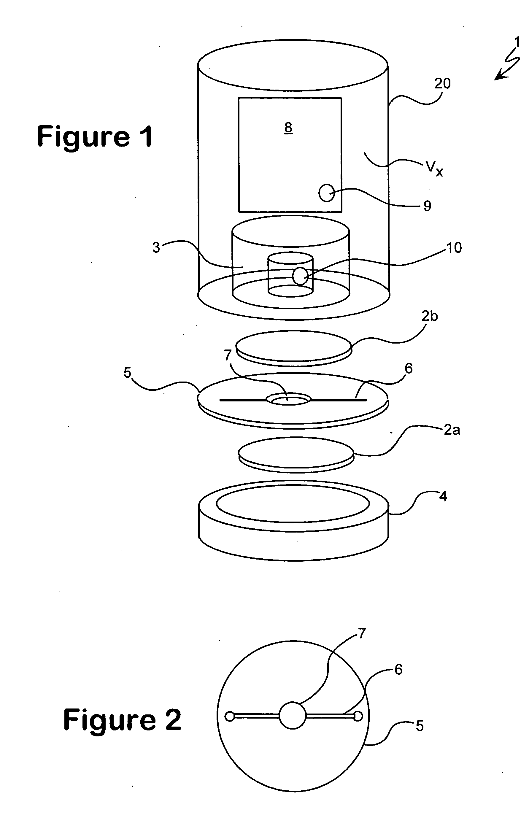
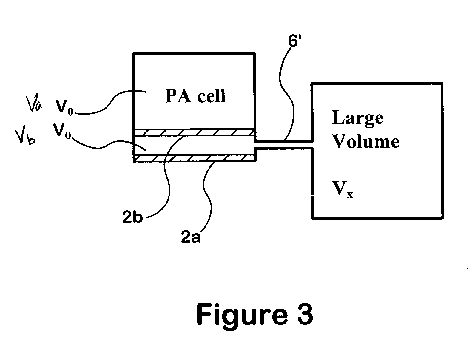
[0023] An embodiment of a diffusive, non-resonant photoacoustic methane detector of the present invention is illustrated in FIG. 1. Reference is made to U.S. Pat. No. 4,740,086, the disclosure of which is incorporated by reference as if fully set forth herein, for the general principles of operation and construction of a photoacoustic sensor / detector. In the embodiment of FIG. 1, an opening within gas inlet 4 of photoacoustic detector 1 is preferably covered with a porous material such as a first metal sinter disk 2a, which permits the diffusion of molecules of the gas species of interest (that is, the analyte gas or gases) into sensing (or measurement) cell 3 of photoacoustic detector 1. As known in the art, first sinter disk 2a acts to attenuate external sources of pressure waves by impeding the progress of air pressure waves incident upon gas inlet 4, while offering only minimal resistance to the diffusion of gas molecules into photoacoustic detector 1 from gas inlet 4. In the em...


PUM

PropertyMeasurementUnit
inner diameteraaaaaaaaaa
thicknessaaaaaaaaaa
thicknessaaaaaaaaaa

Abstract

The present invention relates to a device for accomplishing noise reduction in a photoacoustic gas detector using a sound damping element and / or a background or reference microphone where a preferably larger external volume that acts as a sound damping element (SDE) is coupled to a smaller volume through which the gas diffuses. The coupling is accomplished in such a way that the externally generated sound waves incident upon the photoacoustic detector are adequately attenuated by the larger volume SDE without adversely affecting diffusion of the gaseous species of interest through the smaller volume for measurement by the detector. Preferably this is accomplished by coupling the larger SDE volume to the smaller gas diffusion volume by a long and thin pressure channel. Another photoacoustic detector includes a measuring system to measure the photoacoustic excitation of analyte gas entering the photoacoustic detector, a reference system to measure the effect of pressure waves in the environment, and a system for offsetting an output from the measuring system with an output from the reference system to reduce noise resulting from pressure waves in the environment in an output signal of the photoacoustic detector. The present invention also relates to a device for testing the integrity of a porous member and includes a source of pressure waves and a sensor for measuring a signal resulting from the transmittal of pressure waves from the transmitter. The signal is proportional to pressure losses through the porous member. The pressure losses through the porous member are, in turn, a measure of the degree to which the porous member has become clogged.

Description

FIELD OF THE INVENTION [0001] The present invention relates generally to gas sensors, and, especially, to devices and methods for increasing signal-to-noise ratios in photoacoustic detectors and other gas sensors. BACKGROUND OF THE INVENTION [0002] The use of diffusive gas sensors to detect the concentration level of gaseous species of interest using the photoacoustic effect is well known. For example, U.S. Pat. No. 4,740,086 teaches the use of a diffusive photoacoustic gas sensor to convert the optical energy of an amplitude modulated light source into acoustic energy when the light mechanically and thermically excites the gaseous species of interest as it diffuses into a sensing chamber upon which the light is incident. Sound waves of an intensity corresponding to the concentration level of the gas within the chamber are generated as the light radiation absorbed by the gas creates pressure fluctuations of a magnitude proportional to the number of gas molecules located within the s...

Claims


Application Information

Patent Timeline
Patent Type & Authority Applications(United States)
IPC IPC(8): G01N21/61A61K31/7088A61K38/00G01N29/00A61K39/395A61K45/00A61P35/00C07K14/47C07K14/705C07K16/18C12N1/15C12N1/19C12N1/21C12N5/10C12N15/09C12N15/12C12P21/02C12P21/08C12Q1/02C12Q1/68G01N21/00G01N21/03G01N21/17G01N29/02G01N33/53G01N33/566G01N33/574
CPCA61K38/00G01N21/1702G01N2291/02872C07K14/705A61P35/00
Inventor MOECKLI, MARC ANDREASBOEGLI, URS FREDERICHBLATNICA, LEN JOHNBACHMANN, PHILIPP ALBERTTRACHSEL, HANS
Owner MINE SAFETY APPLIANCES CO
Why Eureka
Try Eureka