
Color determination device and color determination method

a color determination device and color determination technology, applied in the direction of photomechanical treatment, instruments, color signal processing circuits, etc., can solve the problems of inefficiency of color copy machines to operate engines, wrong determination, and inefficiency remains

Inactive Publication Date: 2006-08-31
MURATA MASCH LTD
View PDF5 Cites 21 Cited by
  • Summary
  • Abstract
  • Description
  • Claims
  • Application Information

AI Technical Summary

Benefits of technology

[0014] In order to overcome the problems described above, an advantage of the present invention is to provide a device and a method capable of reducing a calculation amount and automatically determining a color efficiently by improving a method for setting a color determination boundary line corresponding to a threshold value for a color determination.
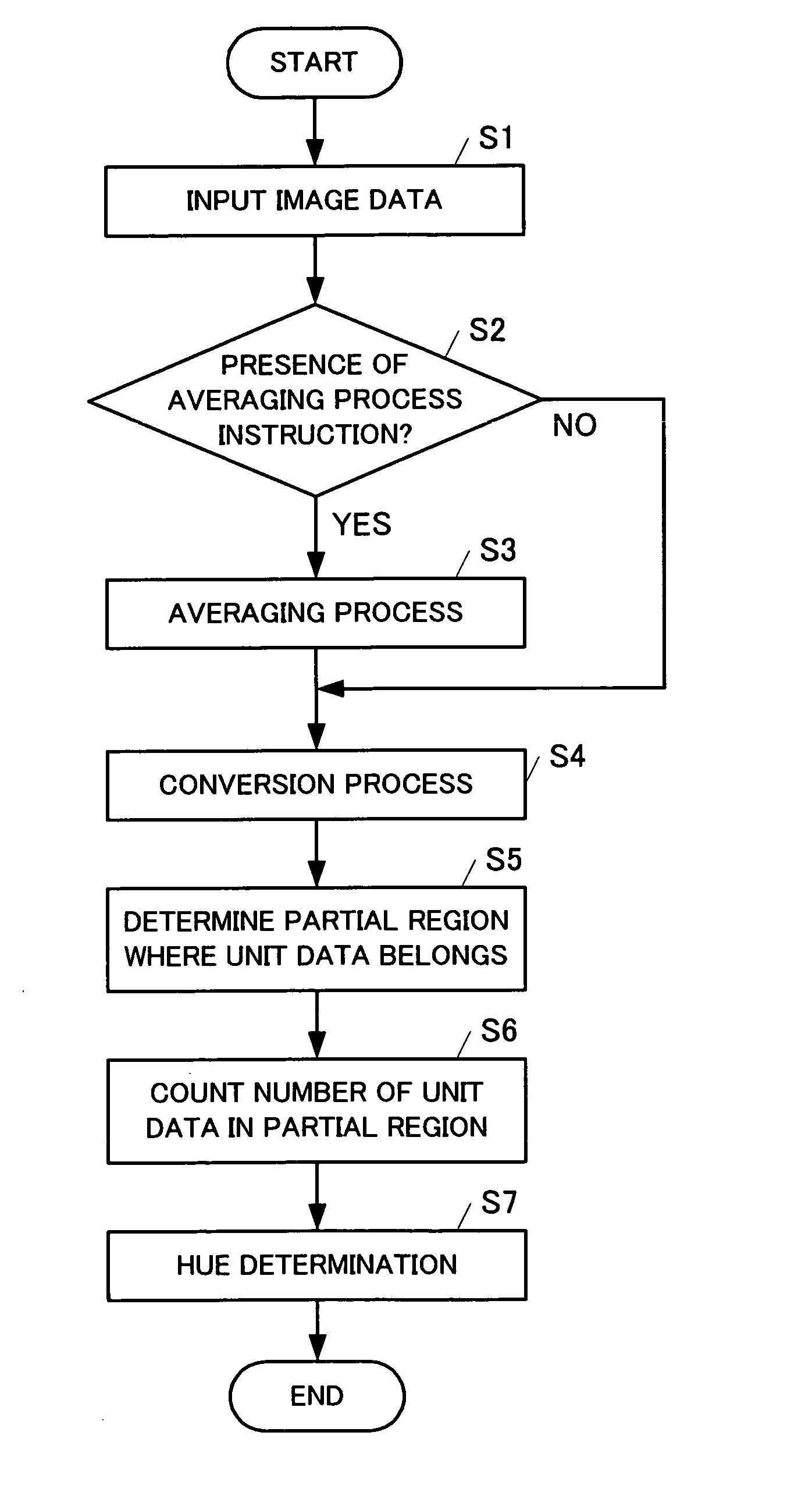
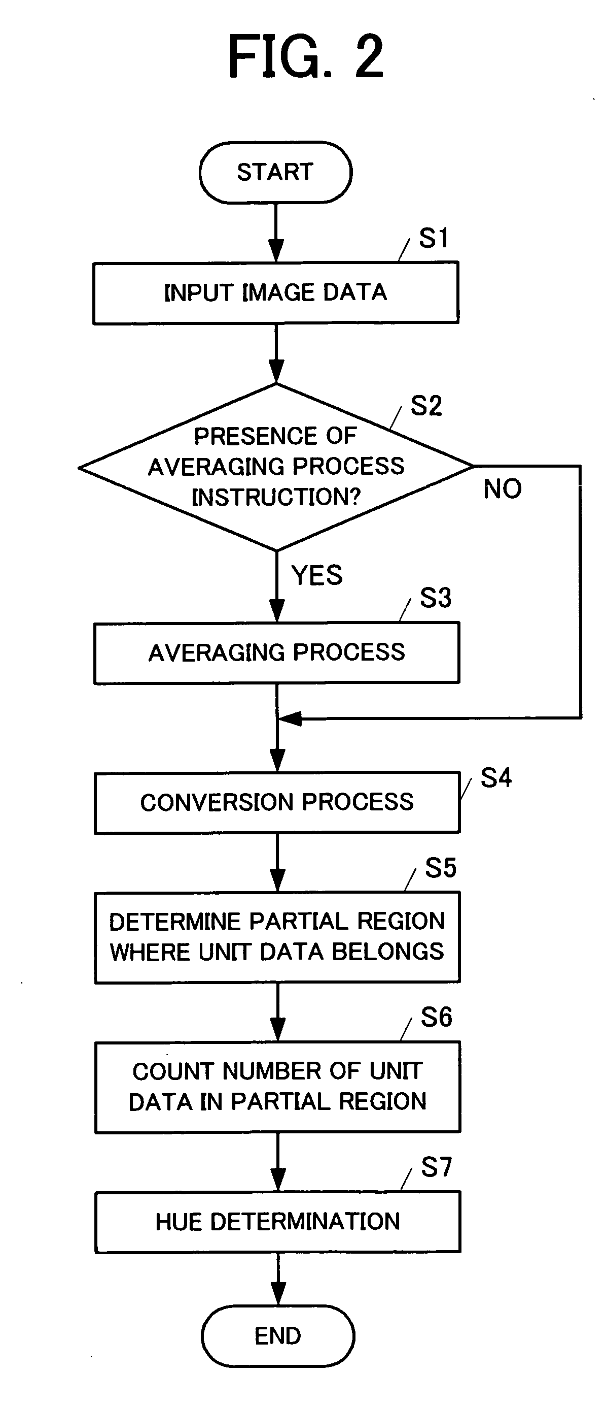
[0015] According to an aspect of the present invention, a color determination device automatically determines a color of an image, and includes a region determination unit, a counting unit and a color determination unit. The region determination unit carries out a determination as to respective image data expressing a color of each portion of a determining image belongs to which one of a plurality of partial regions obtained by dividing a two-dimensional color plane by prescribed color determination boundary lines. The counting unit counts a result of the region determination of the region determination unit. The color determination unit determines a color of the determining image in accordance with a count result of the counting unit. In the color determination device, a gradient of the color determination boundary line with respect to a coordinate axis of the two-dimensional color plane is a rational number.
[0016] The color determination device also includes a conversion unit, which executes a prescribed conversion on the image data. The prescribed conversion includes a rotation on the two-dimensional color plane. After the prescribed conversion is executed on the image data, the region determination unit carries out a determination as to the which one of the plurality of the partial regions the image date belongs.
[0017] According to another aspect of the present invention, the prescribed conversion is an affine conversion in the two-dimensional color plane.
[0018] According to another aspect of the present invention, the prescribed conversion includes a rotational conversion for matching at least one of the color determination boundary lines with either one of coordinate axes in the two-dimensional color plane.
[0019] According to another aspect of the present invention, the color determination device also includes a selectively activating unit, which selectively activates the conversion unit according to which one of a plurality of types of three-dimensional color spaces a color of the determining image is expressed. The color determination device can execute a color determination of the image data based on the plurality of the region boundary lines in accordance with a common comparison standard regardless of which one of the plurality of types of the three-dimensional color spaces the determining image is expressed.

Problems solved by technology

However, when the original image is expressed by a single-color color, it is inefficient for the color copy machine to operate engines of four colors, Yellow (Y), Magenta (M), Cyan (C) and black (K).
When a user carries out a color determination visually, a wrong determination may be made due to the subjectivity of the user.
Since such a key input operation is required, an inefficiency remains.
However, the known devices do not consider sufficiently about how to set a boundary, which is to be a standard for determining the color.
In such a calculation, a calculation for calculating in which direction from an origin a position to be determined is located becomes a complicated calculation since the calculation accompanies a calculation of an irrational number such as an inverse trigonometric function.
As a result, the color determination is inefficient.
The above-described problems occur in the color copy machine and also in other machines such as a color facsimile machine.
For example, in the color facsimile machine, the above-described problems occur when automatically determining by which color a received image will be printed in a single-color printing operation.

Method used


Image

  • Color determination device and color determination method
  • Color determination device and color determination method
  • Color determination device and color determination method

Examples


Embodiment Construction

[0061] (1. Digital Color MFP 100) With reference to the drawings, a description will be made of preferred embodiments of the present invention.

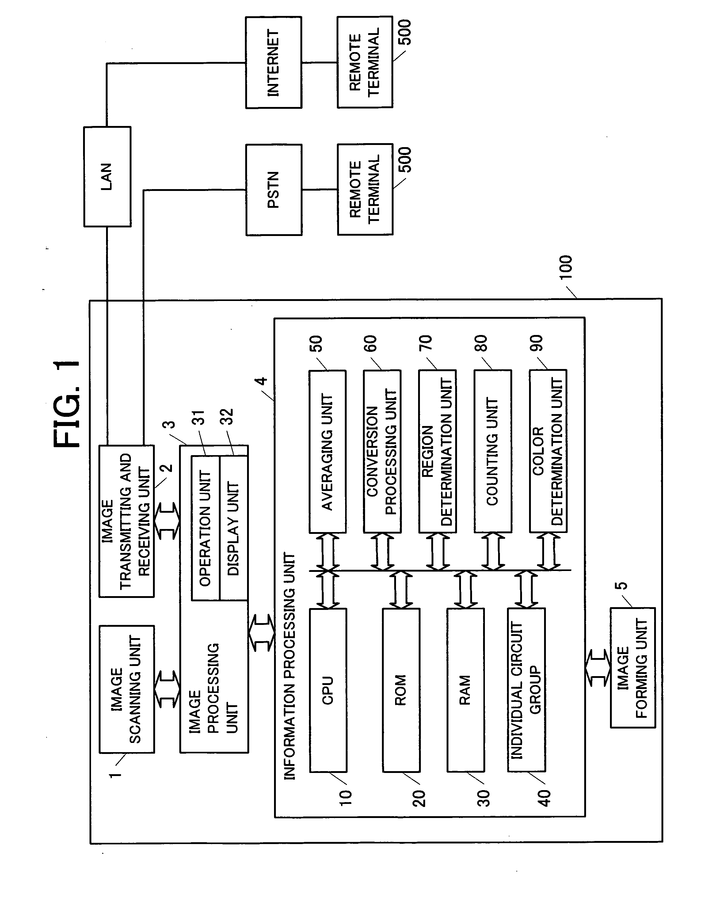
[0062]FIG. 1 illustrates an example of a configuration of a digital color MFP 100 including a facsimile function and a copy function as an example of an image processing device including a function of a color determination device according to a preferred embodiment of the present invention. FIG. 1 illustrates functions particularly relating to the preferred embodiment.

[0063] The digital color MFP 100 includes an image scanning unit land an image transmitting and receiving unit 2. The image scanning unit 1 includes a color scanner function or the like. The image transmitting and receiving unit 2 is used when transmitting and receiving image data between the digital color MFP 100 and a remote terminal 500. The image transmitting and receiving unit 2 includes a Network Control Unit (NCU) (not illustrated) and a Local Area Network InterFace (LA...


PUM


Abstract

A color determination device sections a hue plane, in which unit data constituting determining image data is mapped, into partial regions by a color determination boundary, and carries out a color determination according to a number of unit data belonging to each partial region. A gradient of a hue boundary line is a rational number. For example, an affine conversion or the like is executed on the hue plane, and the color determination boundary line is matched with an axis of the hue plane. Accordingly, a calculation amount is reduced in a determination processing for determining in which partial region the unit data belongs.

Description

BACKGROUND OF THE INVENTION [0001] 1. Region of the Invention [0002] The present invention relates to a device and a method capable of automatically determining a color of an image. [0003] 2. Description of the Related Art [0004] A known image forming device reproduces an original image onto a printing medium such as paper. A color copy machine is one example of such an image forming device. The color copy machine can reproduce a scanned original image by full color. However, when the original image is expressed by a single-color color, it is inefficient for the color copy machine to operate engines of four colors, Yellow (Y), Magenta (M), Cyan (C) and black (K). If an image forming process can be carried out by using only a toner corresponding to a color component included in the original image, the image forming process can be carried out efficiently. [0005] For such a purpose, the color of the original image is required to be determined. When a user carries out a color determinat...

Claims


Application Information

Patent Timeline
IPC IPC(8): G06K9/00
CPCH04N1/56H04N1/6075H04N9/64
Inventor MINAMINO, KATSUSHI
Owner MURATA MASCH LTD
Learn More