Power umbilical for deep water

Inactive Publication Date: 2006-08-31
NEXANS
View PDF4 Cites 40 Cited by
  • Summary
  • Abstract
  • Description
  • Claims
  • Application Information

AI Technical Summary

Benefits of technology

[0015] One main advantage of the invention is that t

Problems solved by technology

Electrical and/or optical cables are not designed to resist the loads applied to the umbilical.
However, under severe conditions such as in use in deep water and/or in dynamic applications increased loads will be applied to the umbilical, due to the w

Method used


Image

  • Power umbilical for deep water
  • Power umbilical for deep water
  • Power umbilical for deep water

Examples


Embodiment Construction

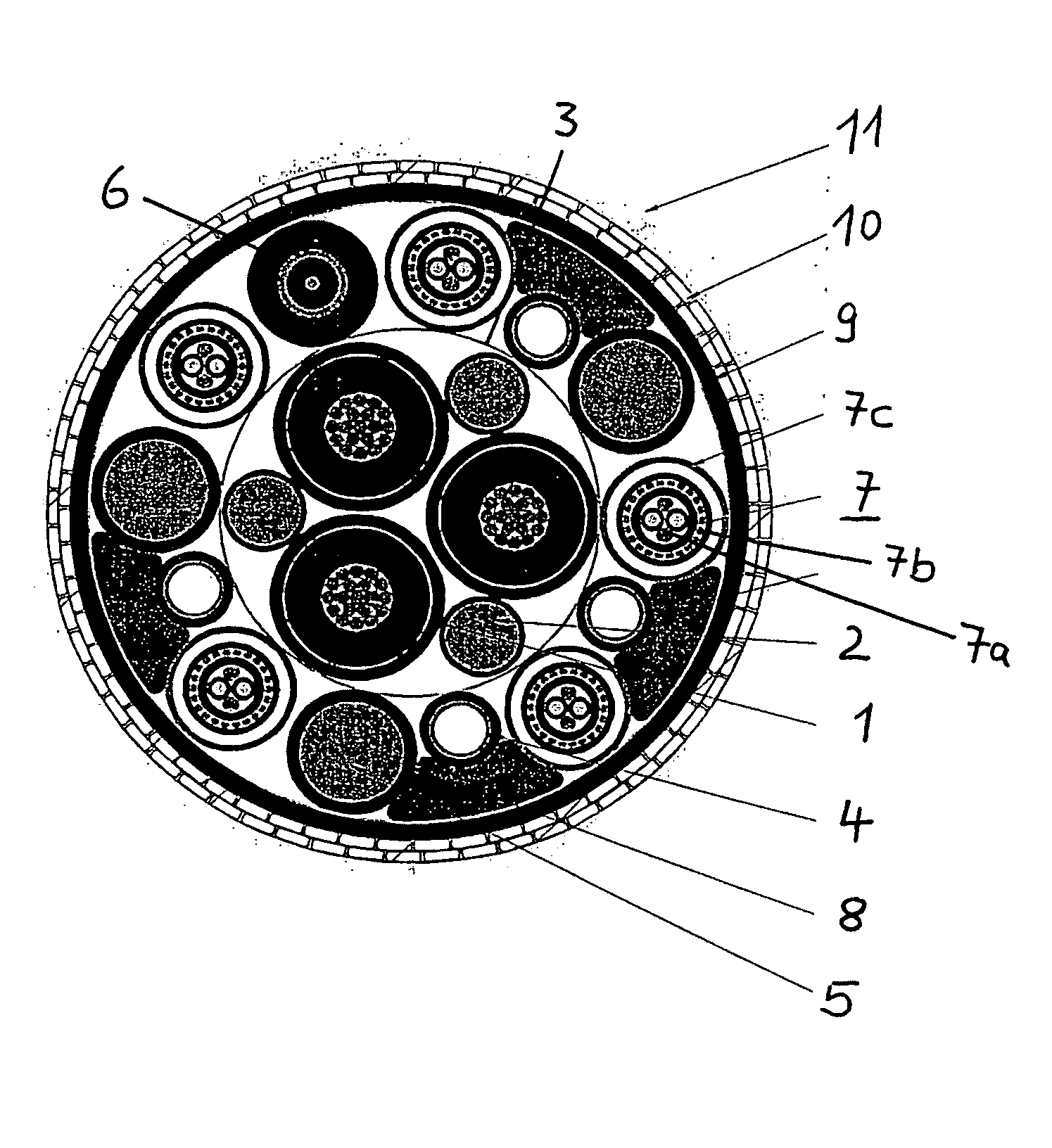
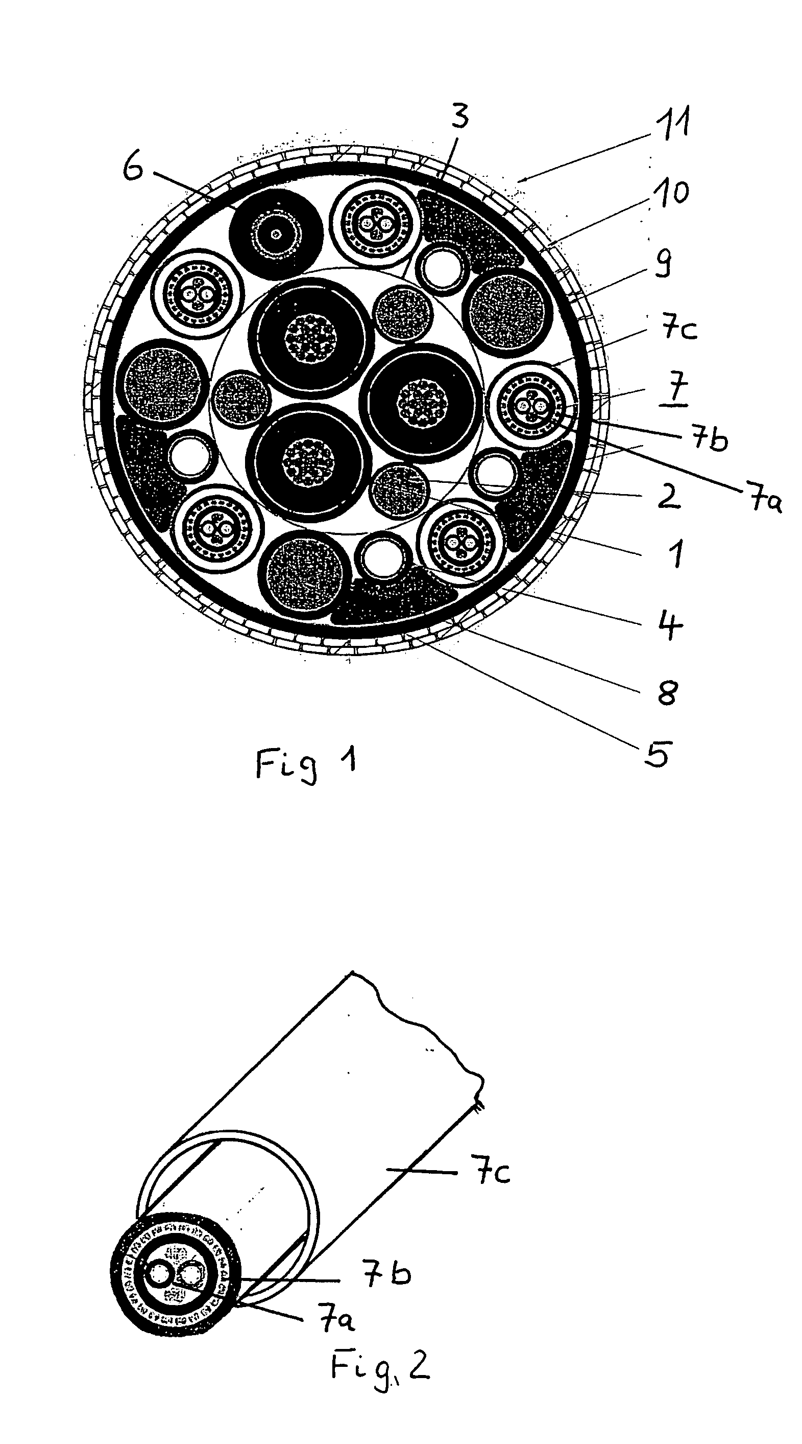
[0020] The umbilical shown in FIG. 1 comprises a center core, which consists of three single core power cables 1, which are stranded to a cable bundle. Three steel ropes 2 sheathed with a layer of thermoplastic material are arranged in interstices between the single core power cables 1. The power cables and the steel ropes 2 are surrounded by a wrapping of a steel tape 3 or other tension proof material. Several elements as steel tubes 4, further steel ropes 5 sheathed with polymeric material, a fiber optic cable 6 and signal cables 7 are laid to the surface of the center core. Fillers 8 are arranged between some of the elements.

[0021] The outer sheath comprises an inner sheath 9, a steel armouring 10 and an outer layer of polyethylene. According to the invention the signal cables 7 consist of an electrical pair 7a or quad which is surrounded by a steel armour 7b and a steel tube 77a. The steel tube 7c consists of super duplex steel. The steel tube 7c may be seamless or may have a l...


PUM


Abstract

A Subsea umbilical includes electrically insulated power conductors, fiber optic elements, electrical signal cables, and fillers within a common outer cover. At least one of the electrical signal cables is enclosed within a dedicated metal tube, and the umbilical is hung off on an offshore platform or the like and the metal tube containing the electrical signal cable is hung oft separately from the umbilical.

Description

RELATED APPLICATION [0001] This application is related to and claims the benefit of priority from Norwegian Patent Application No. 2005 0772, filed on Feb. 11, 2005, the entirety of which is incorporated herein by reference.FIELD OF THE INVENTION [0002] The present invention relates to improvements in umbilicals particularly umbilicals for use in deep water applications. BACKGROUND [0003] An umbilical consists of a group of one or more types of elongated active umbilical elements, such as electrical cables, optical fiber cables or tubes, cabled together for flexibility and over-sheathed and / or armoured for mechanical strength and ballast. Umbilicals are used for transmitting power, signals and fluids to and from a subsea installation via the various elongated umbilical elements. An increasingly important use of umbilicals is the transmission of electrical power to electrical devices on the seabed, and depths of up to 2000 meters are common. [0004] Generally the elements are arranged...

Claims


Application Information

Patent Timeline
IPC IPC(8): G02B6/44H01BH01B7/04H01B9/00
CPCG02B6/4416G02B6/4427H01B7/045H01B9/003H01B9/005
Inventor MJELSTAD, EINAR
Owner NEXANS
Why Eureka
Try Eureka