
Flared Energy Absorbing System and Method

a technology of energy absorption and sliding plate, which is applied in the direction of roadway safety arrangements, roads, construction, etc., can solve the problems of first group of panel support frames and panels that may telescope or collapse relative to each other, and achieve the effect of minimizing the results of collisions

Inactive Publication Date: 2006-08-31
EXODYNE TECH
View PDF80 Cites 33 Cited by
  • Summary
  • Abstract
  • Description
  • Claims
  • Application Information

AI Technical Summary

Benefits of technology

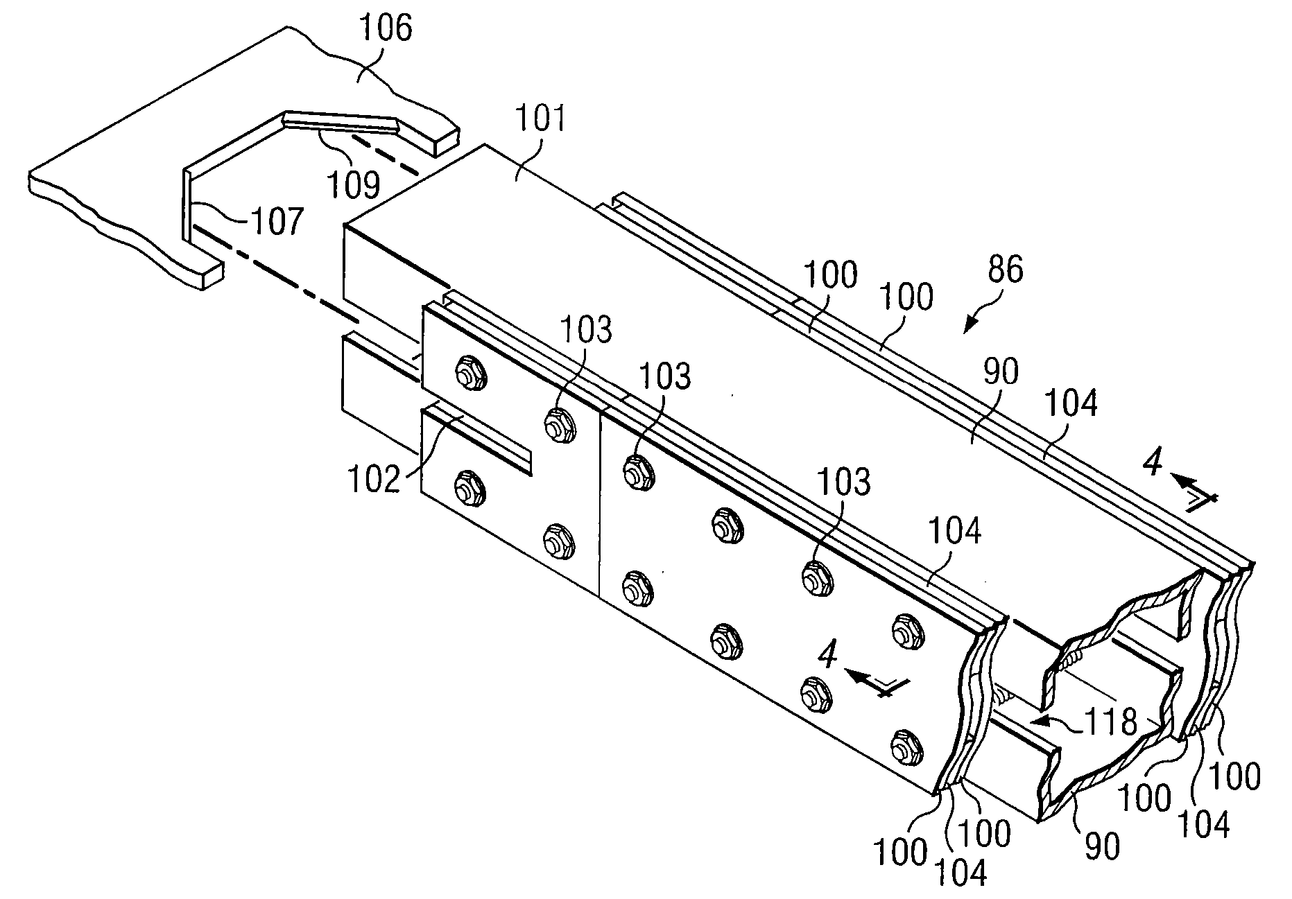
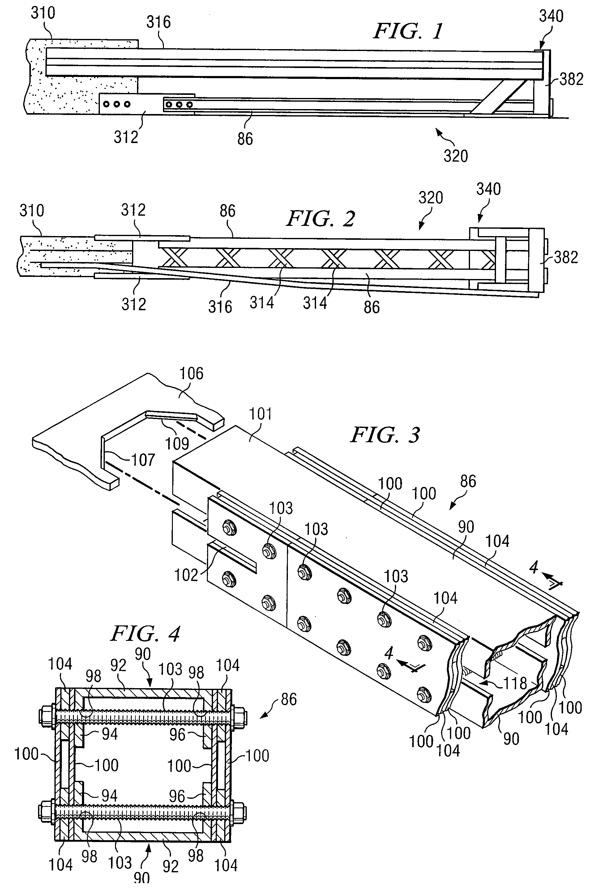
[0009] In accordance with teachings of the present invention, disadvantages and problems associated with previous energy absorbing systems and impact attenuation devices have been substantially reduced or eliminated. One aspect of the present invention includes an energy absorbing system which may be installed adjacent to relatively wide or large roadside hazards to protect occupants of a vehicle during collision with such roadside hazards. The system may include at least one energy absorbing assembly which dissipates energy from a vehicle impacting one end of the system opposite from a roadside hazard. The system may also include panels and associated panel support frames to redirect a vehicle impacting with either side of the system. At least a portion of the panel support frames and panels may be flared or diverge relative to each other to accommodate wide or large roadside hazards.
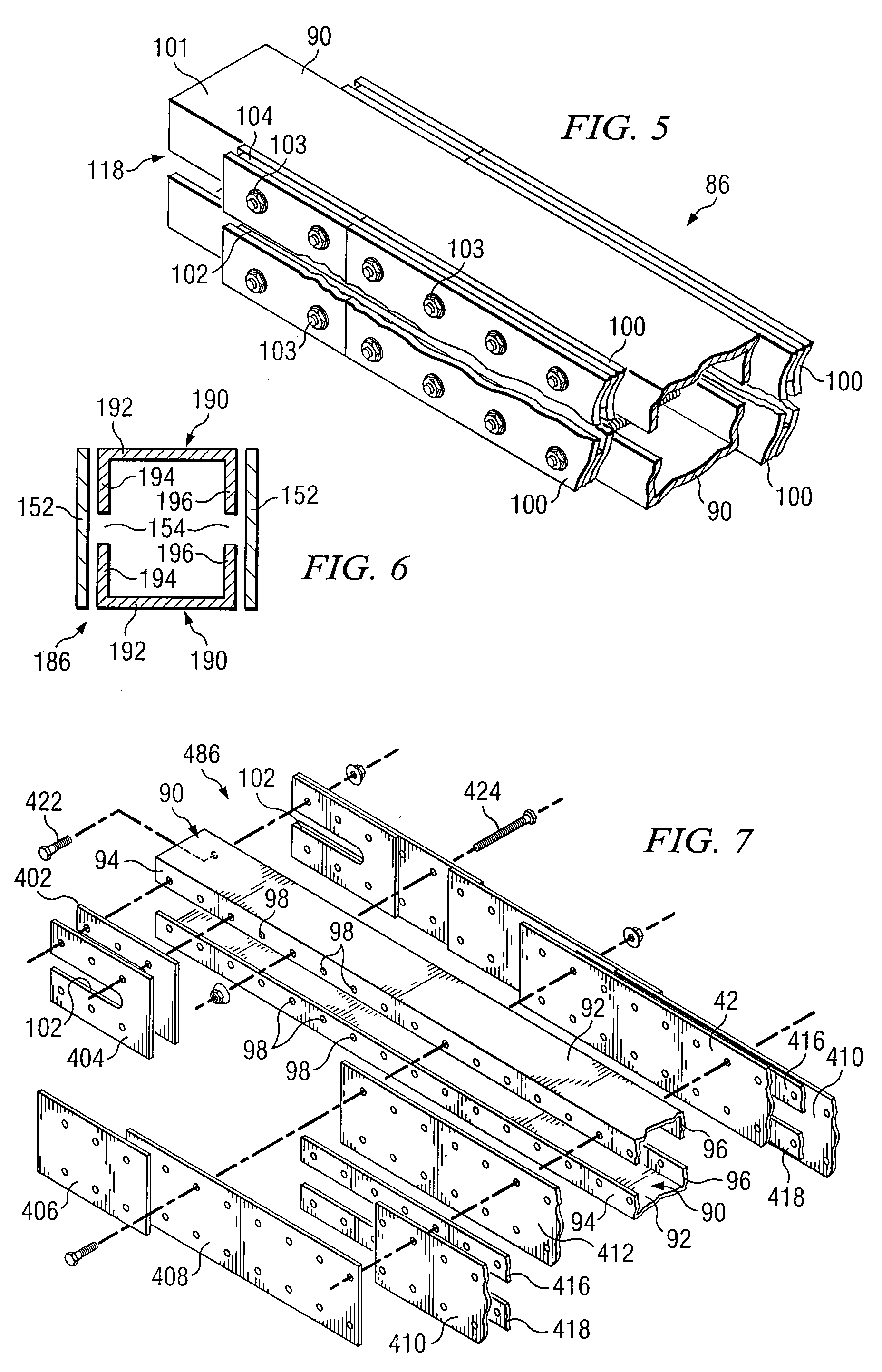
[0010] Another aspect of the present invention includes providing an energy absorbing system having a plurality of panel support frames and panels which may be installed between a roadside hazard and oncoming traffic. At least one set or group of the panel support frames and panels may be slidably disposed relative to each other. At least another set or group of the panel support frames and panels may be securely disposed relative to each other. When a vehicle collides with one end of the energy absorbing system facing oncoming traffic, the first group of panel support frames and panels may telescope or collapse relative to each other. The first group of panel support frames, associated panels and other components of the energy absorbing system cooperate with each other to absorb kinetic energy from the impacting vehicle and provide deceleration within acceptable limits to minimize injury to occupants within the vehicle. The panel support frames and panels also cooperate with each other and other components of the energy absorbing system to direct vehicles away from the roadside hazard and back onto the roadway following a side impact with the energy absorbing system.
[0011] Technical advantages of the present invention include providing a relatively compact energy absorbing system having a variable width to accommodate relatively large, wide roadside hazards and gore areas. Energy absorbing systems incorporating teachings of the present invention may be installed with either symmetric or asymmetric configurations. The energy absorbing system may be fabricated at relatively low cost using conventional materials and processes that are well known to the highway safety industry. The resulting system combines innovative structural and energy absorbing techniques that are highly predictable and reliable. Panel support frames and panels may be installed on location to accommodate the width of an associated roadside hazard or temporary work area.

Problems solved by technology

When a vehicle collides with one end of the energy absorbing system facing oncoming traffic, the first group of panel support frames and panels may telescope or collapse relative to each other.

Method used


Image

  • Flared Energy Absorbing System and Method
  • Flared Energy Absorbing System and Method
  • Flared Energy Absorbing System and Method

Examples


Embodiment Construction

[0060] The present invention and its advantages are understood by referring to FIGS. 1-31 of the drawings, like numerals being used for like and corresponding parts of the drawings.

[0061] Energy absorbing systems 120, 120a and 420 incorporating teachings of the present invention may sometimes be referred to as crash cushions, crash barriers, or roadside protective systems. Energy absorbing systems 120, 120b and 420 may be used to minimize the results of a collision between a motor vehicle (not expressly shown) and various types of roadside hazards. Energy absorbing systems 120, 120a and 420 and other energy absorbing systems incorporating teachings of the present invention may be used for both permanent installation and temporary work-zone applications. Energy absorbing systems 120, 120a and 420 and other energy absorbing systems incorporating teachings of the present invention meet or exceed NCHRP Report 350, Test Level 3 requirements.

[0062] The terms “longitudinal,”“longitudinal...


PUM


Abstract

An energy absorbing system with one or more energy absorbing assemblies is provided to reduce or eliminate the severity of a collision between a moving motor vehicle and a roadside hazard. The energy absorbing system may be installed adjacent to a gore area and other relatively wide roadside hazards. One end of the system facing oncoming traffic is relatively narrow. The width at an opposite end of the system may be varied to accommodate relatively wide or large roadside hazards. A sled assembly may be provided with a cutter plate such that a collision by the motor vehicle with the sled assembly will result in the cutter plate tearing or ripping the energy absorbing element to dissipate energy from the motor vehicle collision.

Description

RELATED APPLICATIONS [0001] This application is a continuation application of U.S. Continuation-in-Part patent application Ser. No. 10 / 379,748 filed Mar. 5, 2003 entitled “Flared Energy Absorbing System and Method” now U.S. Pat. No. ______. [0002] This application is related to Divisional patent application Ser. No. 11 / 185,255 filed Jul. 20, 2005 entitled “Flared Energy Absorbing System and Method” now U.S. Pat. No. ______.TECHNICAL FIELD OF THE INVENTION [0003] This invention relates in general to energy absorbing systems, and more particularly to an energy absorbing system used to reduce severity of a collision between a moving motor vehicle and a hazard located adjacent to a roadway. BACKGROUND OF THE INVENTION [0004] Various impact attenuation devices and energy absorbing systems have been used to prevent or reduce damage resulting from a collision between a moving motor vehicle and a fixed roadside hazard or obstacle. Examples of prior impact attenuation devices and energy abso...

Claims


Application Information

Patent Timeline
IPC IPC(8): E01F15/00
CPCE01F15/146
Inventor ALBRITTON, JAMES R.
Owner EXODYNE TECH
Learn More