
Fluid operating valve

a technology of operating valve and valve body, which is applied in the direction of valve details, valve arrangement, operating means/release devices, etc., can solve the problems of increasing cost, complicated piping, and large piping spa

Inactive Publication Date: 2006-09-07
ASAHI YUKIZAI KOGYO CO LTD
View PDF4 Cites 49 Cited by
  • Summary
  • Abstract
  • Description
  • Claims
  • Application Information

AI Technical Summary

Benefits of technology

[0008] An object of the present invention is to obviate the aforementioned problem of the prior art and to provide a fluid-operated valve which has a function to be fully closed in the case of an emergency and is capable of exhibiting a high sealing performance even in a situation where the fluid pressure is high. Another object of the present invention is to provide a fluid-operated valve which has the aforementioned configuration and is capable of adjusting and holding the opening degree of the valve at any of a fully closed state, a fully opened state and an arbitrary intermediate-opening degree.
[0011] As the first piston is urged away from the first valve chamber by the spring in the fluid-operated valve according to the present invention, the valve body connected to the first piston through the valve stem is pressed against the valve seat to thereby fully close the valve, when the working fluid such as air or oil is not supplied to the fluid-operated valve. As a result, in case of an emergency in which the working fluid is not supplied to the fluid-operated valve, the fluid is prevented from flowing through the valve.
[0013] Especially in the case where a pressure-receiving area of the diaphragm for receiving the pressure of the fluid in the first valve chamber is designed to be larger than that of the valve body, the force exerted in the direction to press the valve body against the valve seat, in the fully closed state, always exceeds the force exerted in the direction to move the valve body away from the valve seat, and therefore a high sealing performance can be exhibited.
[0015] If the valve is adapted so that the valve body can be moved away from the valve seat by bringing the adjustment screw mounted on the second piston of the second cylinder chamber into contact with the first piston, the valve opening degree can be adjusted by adjusting the amount of projection of the adjustment screw from the second piston, thereby making it possible to adjust the valve to an intermediate opening degree between the fully closed state and the fully opened state. If the other end of the adjustment screw is positioned outside the valve housing, the amount of projection of the adjustment screw from the second piston can be adjusted without disassembling the valve housing, and therefore the valve opening degree can be adjusted more easily.
[0017] If the second valve chamber is formed in the bottom of the valve housing, the need of the piping for connecting the second valve chamber and a tank, etc. can be eliminated when the valve is placed directly on the tank, etc.

Problems solved by technology

However, this method requires two or more two-way valves to be disposed.
Therefore, it has problems of complicating the piping work, requiring a large piping space, and further increasing the cost due to the need of a plurality of valves and the corresponding amount of piping materials.
However, this three-position open-and-close valve cannot be fully closed in a situation where the working fluid is not injected.
This results in a problem that, in the case of emergency where the supply of the working fluid stops, for example, the valve is kept slightly opened and the fluid such as a chemical liquid flowing through the line continues to flow out from the line.
Therefore, especially in the case where the fluid pressure is high, the force of the fluid pushing up the valve body exceeds the force of the fluid pressing the valve body against the valve seat, thereby resulting in a problem that a leakage is liable to occur.

Method used


Image

  • Fluid operating valve
  • Fluid operating valve
  • Fluid operating valve

Examples


Embodiment Construction

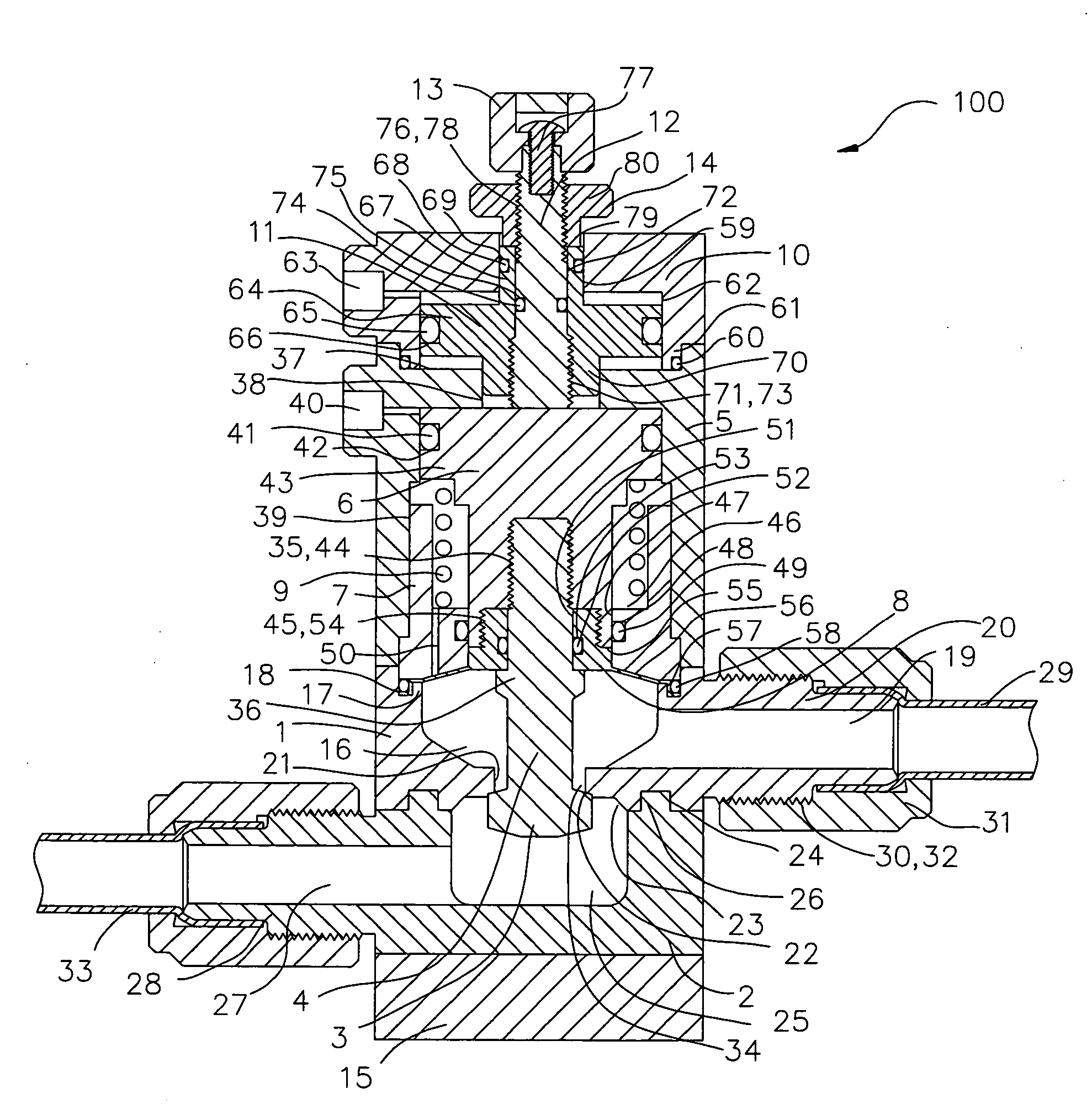
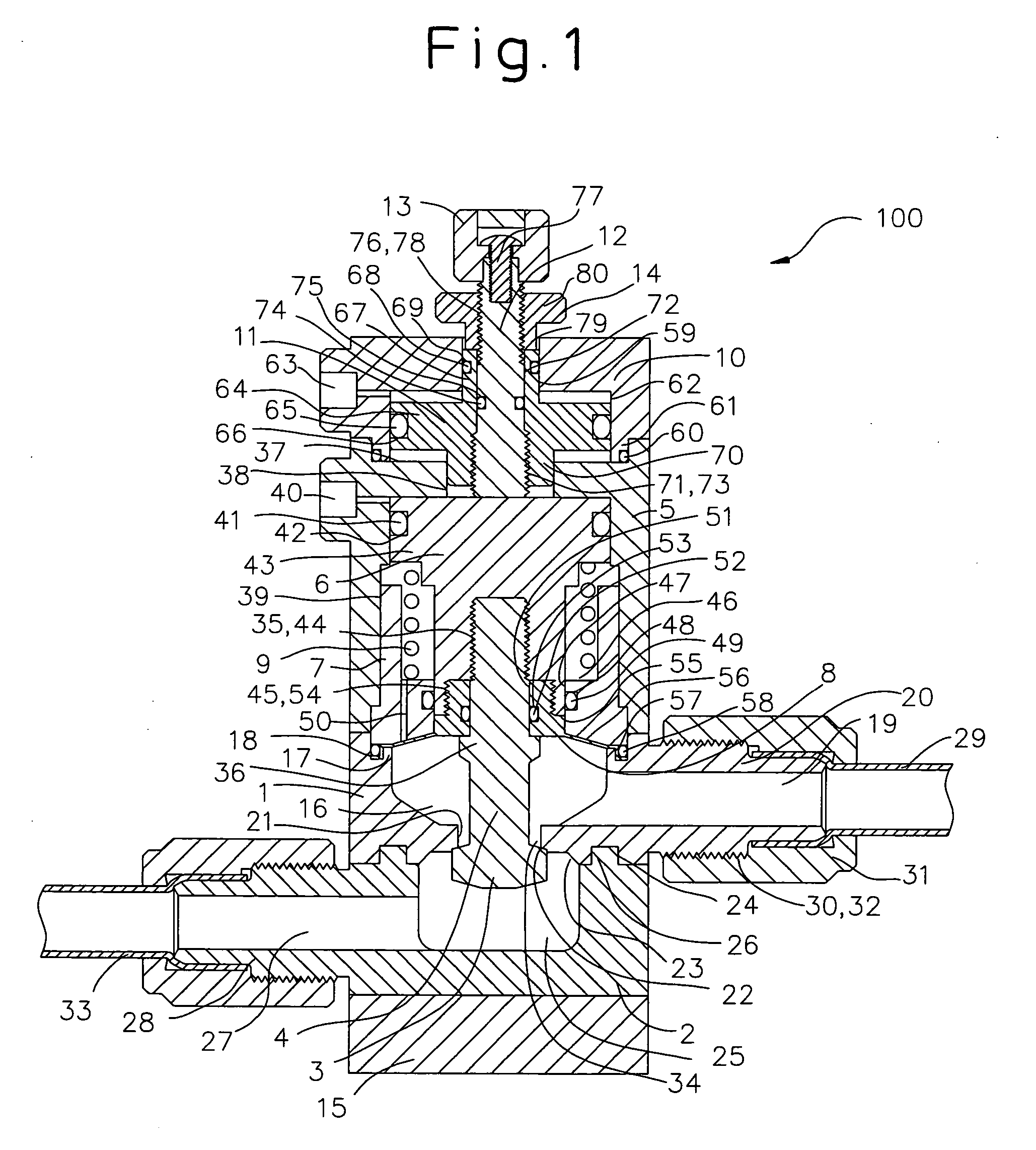
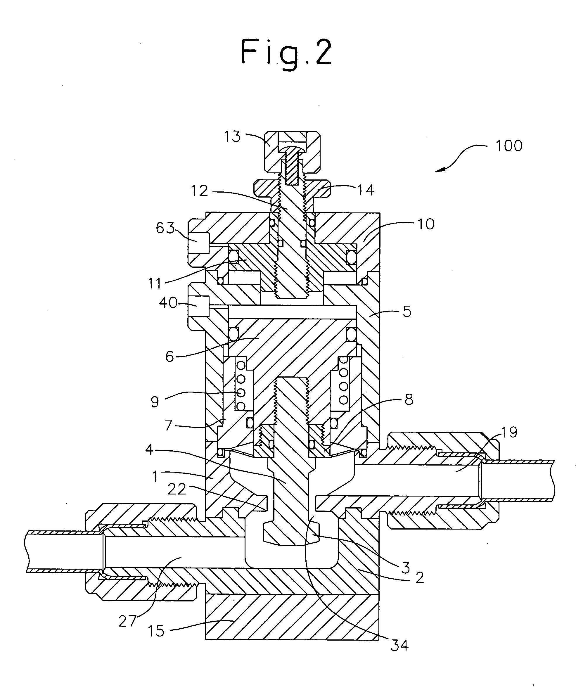
[0026] Several embodiments of the present invention will be described below with reference to the drawings, but the present invention is, of course, not limited to these embodiments.

[0027] An air-operated value 100 includes a valve housing having an upper body 1, a lower body 2, a valve body 3, a first cylinder 5, a second cylinder 10 and a base 15. A substantially bowl-shaped first valve chamber 16 with an open upper side is formed in the upper body 1. A flat portion 17 is formed on the upper body 1 so as surround the outer periphery of the top portion of the first valve chamber 16, and an annular groove 18 is formed on the upper body 1 so as to surround the outer periphery of the flat portion 17. A joint 20 is projected from the side surface of the upper body 1, and a first flow passage 19 formed in the joint 20 is in communication with the first valve chamber 16. A through-hole 21 leading to the first valve chamber 16 is formed in the bottom of the upper body 1, and a valve seat...


PUM


Abstract

A fluid-operated valve comprises a first valve chamber (16) and a second valve chamber (25) communicating with each other through a through-hole (21), a first cylinder chamber (39) formed adjacent to the first valve chamber (16) and accommodating a first piston (6) so as to be slidable therein, a valve body (3) positioned in the second valve chamber (25) and adapted to come into contact with or move away from a valve seat (22) around the through-hole (21), a valve stem (4) having one end connected to the first piston (6) and the other end connected to the valve body (3), and an annular diaphragm (8) having an inner peripheral portion fixed to the valve stem (4) and an outer peripheral portion fixed to the inner peripheral surface of the first valve chamber (16). The first piston (6) is urged by a spring (9) to bring the valve body (3) into contact with the valve seat (22). The first piston (6) is moved by supplying the working fluid into the first cylinder chamber (39) through the working fluid supply port of a first cylinder (5) to move the valve body (3) away from the valve seat (22).

Description

TECHNICAL FIELD [0001] The present invention relates to a fluid-operated valve, having first and second flow passages making up an outlet and an inlet for the fluid, which is used for fluid transportation in various industrial fields, such as chemicals, semiconductor production, food processing, biotechnology and the like. BACKGROUND ART [0002] In various conventional chemical liquid lines and pure water lines, as shown in FIG. 6, for example, a method is employed in which, in order to supply a predetermined amount of a fluid into a tank 108 with high accuracy, a plurality of two-way valves 106, 107 of different diameters are disposed in parallel to each other and are opened in the initial stage thereby to fill the tank 108 at a large flow rate, while the large-diameter two-way valve 107 is closed and the small-diameter two-way valve 106 alone is opened in the last stage, thereby finely adjusting the total capacity. [0003] However, this method requires two or more two-way valves to ...

Claims


Application Information

Patent Timeline
IPC IPC(8): F16K51/00F16K31/122
CPCF16K31/1221F16K31/1225F16K31/122
Inventor HAMADA, TAKESHIHANADA, TOSHIHIRO
Owner ASAHI YUKIZAI KOGYO CO LTD
Features
  • Generate Ideas
  • Intellectual Property
  • Life Sciences
  • Materials
  • Tech Scout
  • Unparalleled Data Quality
  • Higher Quality Content
  • 60% Fewer Hallucinations
Learn More