
Self-test method for antennas

a self-testing and antenna technology, applied in the field of radio communication equipment, can solve problems such as inability to measure instruments, influence on system performance, communication link loss,

Inactive Publication Date: 2006-09-07
NOKIA CORP
View PDF17 Cites 114 Cited by
  • Summary
  • Abstract
  • Description
  • Claims
  • Application Information

AI Technical Summary

Benefits of technology

[0008] It is therefore an object of the present invention to provide an improved radio communication apparatus and method for testing such an apparatus, by means of which antenna failures, such as poor or missing antenna contacts can be reliably detected without requiring additional hardware circuits.
[0017] Accordingly, poor or missing antenna contacts can be detected in a simple manner without requiring specific test equipment or measuring instruments. Antenna and antenna connections can even be tested without extra components of the communication apparatus, since the method or procedure can be implemented by a pure software routine. With the proposed self-test method, information about isolation between antennas can be collected and based on collected information and predetermined thresholds, failing antennas or antenna connections can be isolated.
[0024] Furthermore, the checking method may be initiated in response to an output of an acceleration sensor. This provides the advantage that a self-test is automatically initiated after the communication apparatus or terminal device has been dropped.

Problems solved by technology

Therefore, small connection errors or other antenna errors may have such a negative influence on the system performance that the communication link can be lost.
However, at the label place there are usually no measurement instruments available.
Therefore, a problem arises how to test these antennas in production and in customer care service centers in an easy way at low cost and multiple times with high reliability.
However, the Antenna system functionality is degraded and not working as tested if any of these connections is poor or disconnected.
However, this method needs additional circuitry to measure reflected power.
Moreover, transmitter this method is not useful in connection with antennas which have separate feeding for the receiver.

Method used


Image

  • Self-test method for antennas
  • Self-test method for antennas
  • Self-test method for antennas

Examples


Embodiment Construction

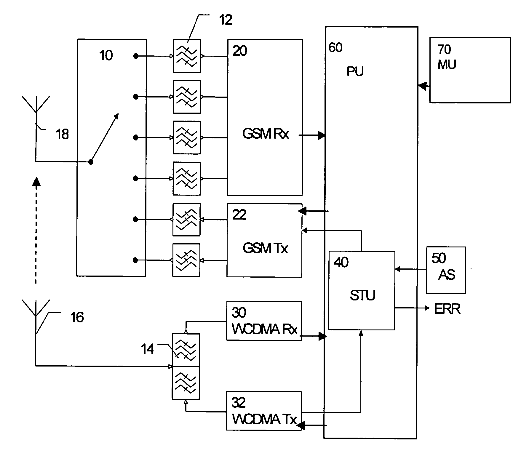
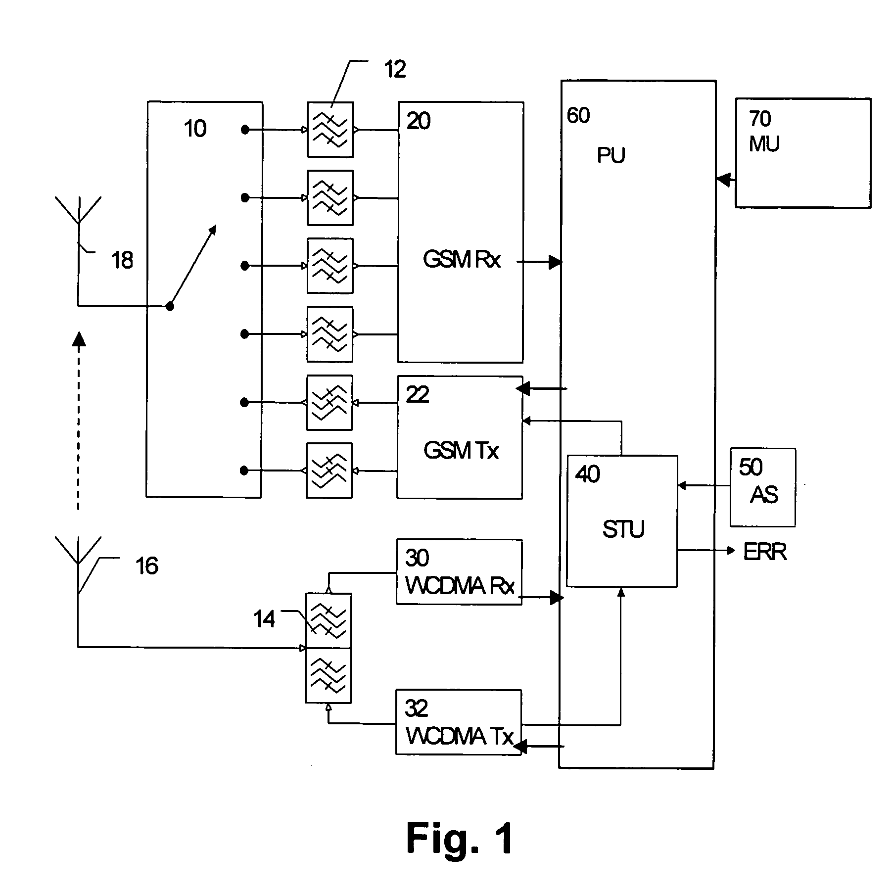
[0037] The preferred embodiments will now be described on the basis of a combined GSM and a WCDMA mobile phone front-end architecture or transceiver implemented as shown in the first preferred embodiment of FIG. 1.

[0038] In particular, the FIG. 1 shows a full-duplex mobile phone front-end architecture or transceiver wherein the WCDMA duplex bands comprise a receiving band ranging from 2110 MHz to 2170 MHz and a transmission band ranging from 1920 MHz and 1980 MHz. The WCDMA signals are received by a separate WCDMA antenna 16 which is directly connected to a WCDMA duplexer 14 con-Fig.d to switch WCDMA signals received via a common transmission and receiving path to the upper receiving path, and to switch WCDMA transmission signals received via the lower transmission path to the WCDMA antenna 16 via the combined transmitting and receiving path.

[0039] Furthermore, a GSM front-end portion is shown, in which GSM signals received via GSM antenna 18 are selectively connected by a GSM ant...


PUM


Abstract

The present invention relates to a radio communication apparatus for checking antenna interface connections of first antenna means of the radio communication apparatus, wherein a predetermined signal is transmitted at a frequency within a reception band of the first antenna means by using a second antenna means of the radio communication apparatus. The transmitted predetermined signal is received through the first antenna means to obtain a reception output which is compared with the predetermined signal. Thereby, a self-test option can be provided in the communication apparatus, e.g. mobile phone, so that no extra components are required during manufacturing and antenna operation can be continuously monitored during usage.

Description

FIELD OF THE INVENTION [0001] The present invention relates to a radio communication apparatus and a method for checking operability of first antenna means thereof. In particular, the present invention relates to a self-test method for checking connection quality of antenna connections for cellular communication systems. BACKGROUND OF THE INVENTION [0002] Antennas represent a key element in mobile communications as interface between the system and the air. This transition between guided waves and radiated waves involves all wireless systems and must be carried out in an effective way. In this sense, communication systems are deeply dependent on the antenna performance. Therefore, small connection errors or other antenna errors may have such a negative influence on the system performance that the communication link can be lost. [0003] New antenna subsystems with multifunction, multiband etc. will be able to satisfy the necessities for emerging multimedia applications. Typical mobile ...

Claims


Application Information

Patent Timeline
IPC IPC(8): G01R31/11
CPCH01Q1/243H04B17/20H04B17/19
Inventor LEINONEN, MARKOROUSU, SEPPO
Owner NOKIA CORP
Learn More