Clock generating apparatus and method in optical storage system

a clock generator and optical storage system technology, applied in the direction of generating/distributing signals, pulse automatic control, instruments, etc., can solve the problems of still existance of problems, insufficient accuracy of the method of utilizing the pulse width to evaluate the frequency, etc., and achieve the effect of high resolution

Active Publication Date: 2006-09-07
REALTEK SEMICON CORP
View PDF5 Cites 39 Cited by
  • Summary
  • Abstract
  • Description
  • Claims
  • Application Information

AI Technical Summary

Benefits of technology

[0007] It is therefore one of the objectives of the claimed invention to provide a clock generator and clock generating method having a high resolution FD.

Problems solved by technology

However, according to the aforementioned, there still exists a problem.
Therefore, the method of utilizing the pulse width to evaluate the frequency is not satisfactorily accurate.

Method used


Image

  • Clock generating apparatus and method in optical storage system
  • Clock generating apparatus and method in optical storage system
  • Clock generating apparatus and method in optical storage system

Examples


Embodiment Construction

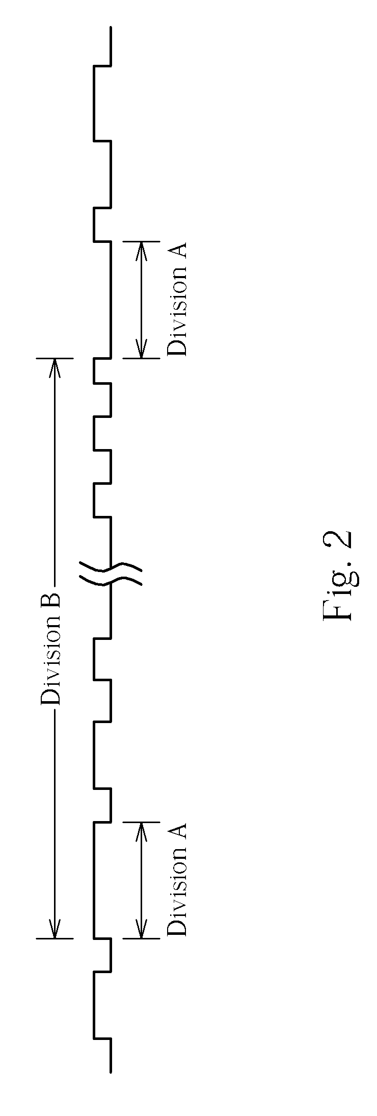
[0016] Please again refer to FIG. 2. As shown in FIG. 2, a DVD system (such as a DVD optical disk drive) not only defines a 14T synchronous pattern (section A), but also defines a 1488T interval (section B) between two synchronous patterns (that is, a frame). Utilizing the 1488T interval to lock on the frequency can reduce the potential error of frequency estimation to 1 / 1488. Therefore, the following embodiments of the present invention utilize the corresponding interval between two synchronous patterns to evaluate the frequency so that the resolution of the FD is raised.

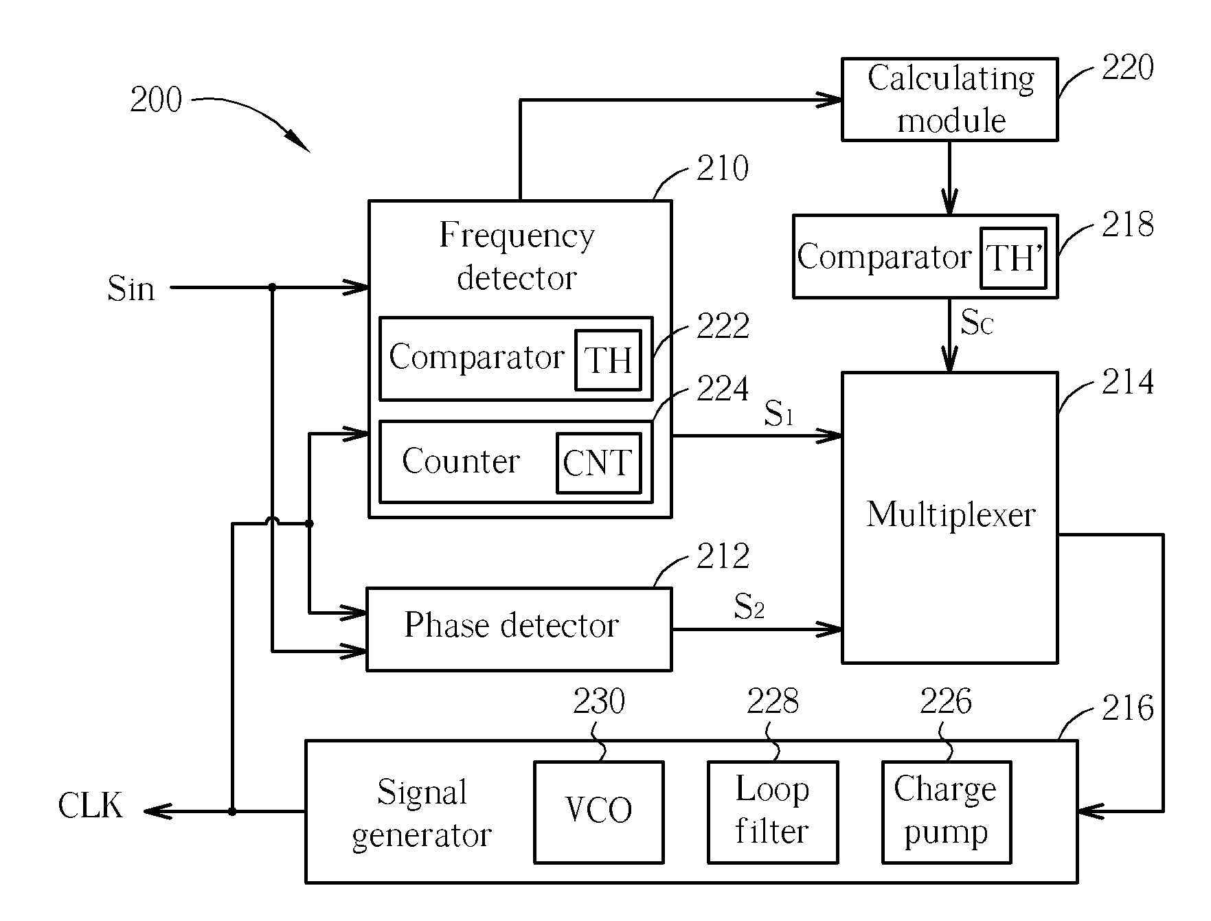
[0017] Please refer to FIG. 3, which shows a clock generator 200 according to an embodiment of the present invention. The clock generator 200 comprises an FD 210, a PD 212, a multiplexer 214 coupled to the FD 210 and the PD 212, a signal generator 216 coupled to the multiplexer 214, a comparator 218 coupled to the multiplexer 214, and a calculating module 220 coupled to the FD 210 and the comparator 218. In this e...


PUM


Abstract

A clock generating apparatus and clock generating method of an optical disc drive for calibrating a clock signal according to an input signal. The clock generating apparatus includes a frequency detector for detecting sampling times in a duration when the clock signal samples an interval between two synchronization patterns of the input signal, and for generating a first adjusting signal according to the sampling times, and a signal generator electrically coupled to the frequency detector for calibrating the clock signal according to the first adjusting signal.

Description

BACKGROUND OF THE INVENTION [0001] 1. Field of the Invention [0002] The invention relates to optical storage systems, and more particularly, to a clock generator and clock generating method of optical storage systems. [0003] 2. Description of the Prior Art [0004] A phase lock loop (PLL) is an essential component of an optical disk drive, for generating needed clock signals for the operation of the optical disk drive. In this way, the optical disk drive can sample the stored data on the optical disk according to the clock signal generated by the PLL. Please refer to FIG. 1, which is a diagram of a typical PLL 100. The PLL 100 comprises a phase detector (PD) 110, a frequency detector (FD) 112, a charge pump 114, a loop filter 116, and a voltage-controlled oscillator (VCO) 118. The functions and operations of the charge pump 114, the loop filter 116, and the VCO 18 are well known and details are thus omitted herein. Because the frequency of the signal read by the optical disk drive fro...

Claims


Application Information

Patent Timeline
Patent Type & Authority Applications(United States)
IPC IPC(8): H03L7/06
CPCH03L7/113
Inventor YEN, KUANG-YU
Owner REALTEK SEMICON CORP
Why Eureka
Try Eureka