Liquid droplet ejecting unit, image forming apparatus and valve

a technology of liquid droplets and ejectors, applied in printing and other directions, can solve the problems of increased pressure loss, air bubbles, poor readiness of the check valve, etc., and achieve the effect of improving the readiness of the valve and increasing the pressure loss

Inactive Publication Date: 2006-09-07
FUJIFILM BUSINESS INNOVATION CORP
View PDF7 Cites 8 Cited by
  • Summary
  • Abstract
  • Description
  • Claims
  • Application Information

AI Technical Summary

Benefits of technology

[0010] The present invention has been made in view of the above facts and the need to improve the readiness of a valve for the checking operation when a liquid flows backward, without being accompanied by an increased pressure loss during an opening operation of the valve when the liquid flows backward.
[0013] A third aspect of the present invention provides a valve comprising: a valve body provided in a substantially vertically extending liquid flow path that permits a liquid to flow downward and configured such that an inlet port into which the liquid flows from the liquid flow path is smaller in cross-sectional size than an outlet port from which the liquid that flows into the inlet port flows out; and a floating member that is larger in cross-sectional size than the inlet port and smaller in cross-sectional size than the outlet port and has a lower specific gravity that the liquid such that the floating member floats in the liquid in the valve body and is capable of closing the inlet port.

Problems solved by technology

Obviously, this check valve has poor readiness of the checking operation.
Thus, a time lag occurs between when the suctioning operation is started and when the check valve is closed, and there is a problem such that air bubbles occur as a result of ink flowing backward during the time lag.
However, in such a case, there is another problem that an increased pressure loss is caused due to an increase in the load of an opening operation when the ink is fed in a normal direction.

Method used


Image

  • Liquid droplet ejecting unit, image forming apparatus and valve
  • Liquid droplet ejecting unit, image forming apparatus and valve
  • Liquid droplet ejecting unit, image forming apparatus and valve

Examples


first embodiment

[0030] Description will now be made of the present invention with reference to the drawings

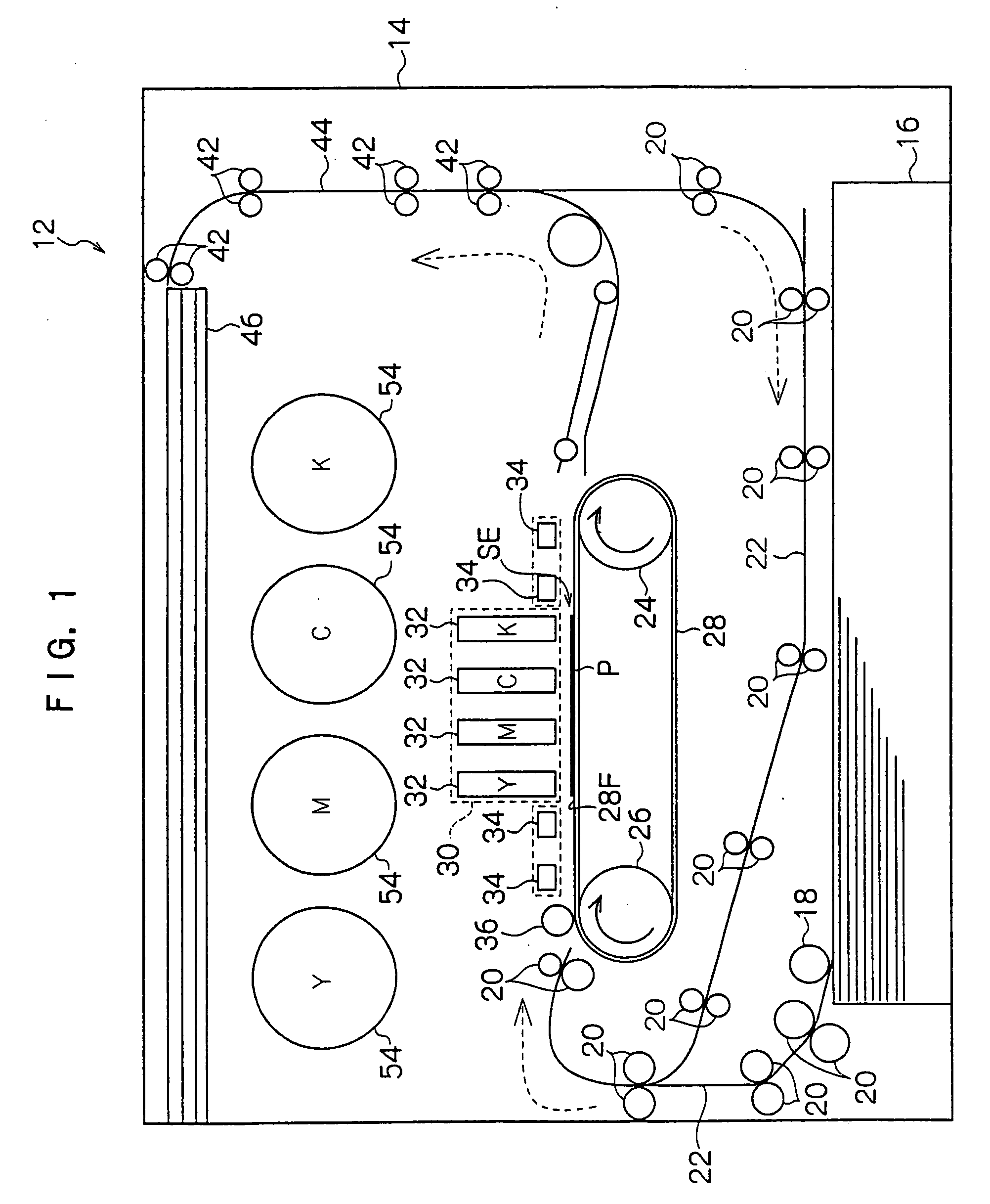
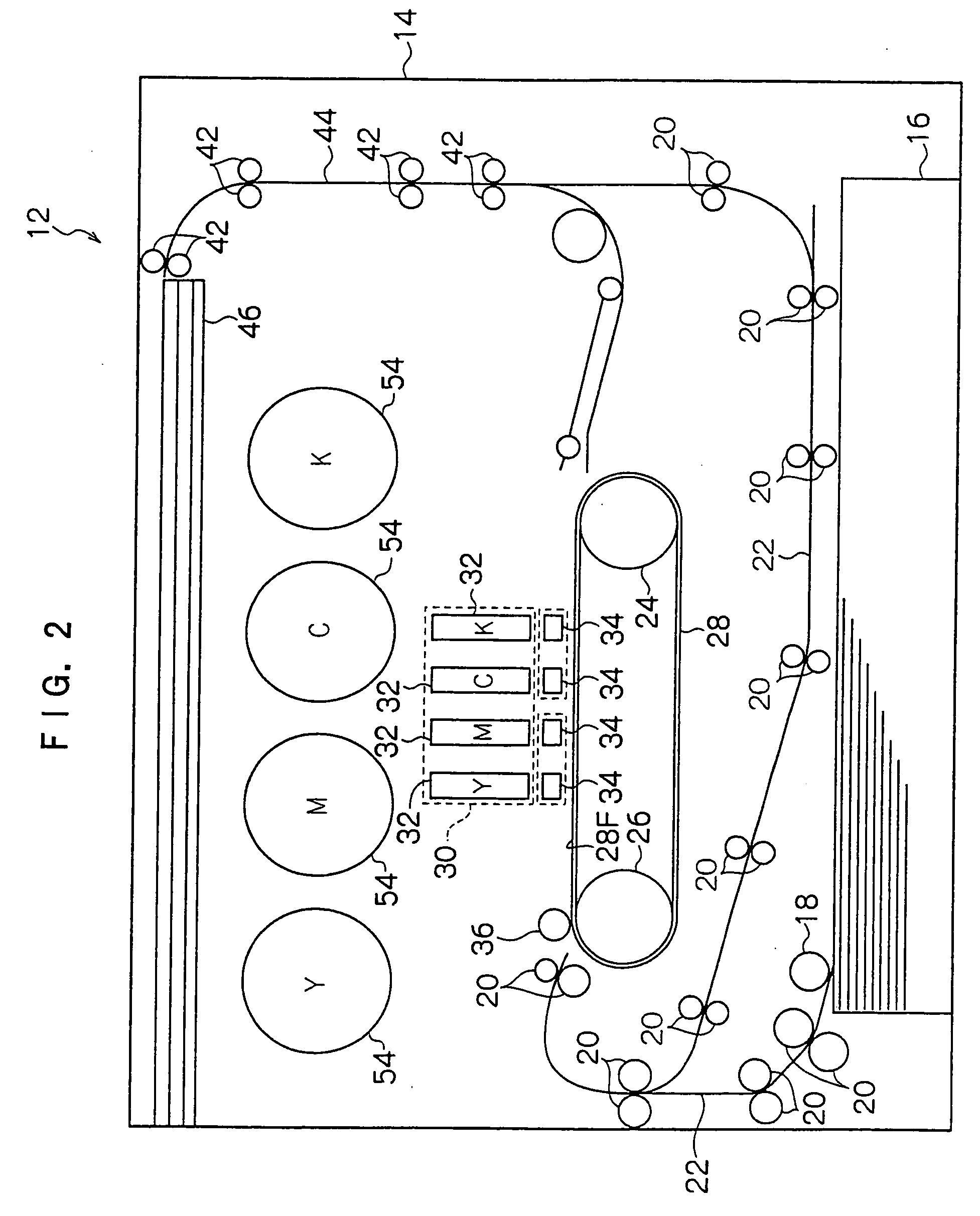
[0031] Referring to FIG. 1, there is shown an inkjet recording apparatus 12 according an embodiment of the present invention wherein a paper feed tray 16 is provided on a bottom portion within a housing 14 such that paper P layered in the paper feed tray 16 can be taken out therefrom on a per sheet basis by a pickup roll 18. The paper P taken out is conveyed by means of plural conveyor roller pairs 20 forming a predetermined conveyance path 22.

[0032] Above the paper feed tray 16 is provided an endless conveyor belt 28 entrained about a driving roll 24 and a driven roll 26. Further, above the conveyance belt 28 is provided a recording head array 30 which is disposed in opposing relationship to a flat portion 28F of the conveyor belt 28. This region in which the recording head array is in opposition to the flat portion 28F of the conveyor belt 28 is an ejection region SE in which ink droplets a...


PUM


Abstract

A liquid droplet ejecting unit is disclosed wherein plural liquid droplet ejecting sub-units are provided which are arrayed in a direction substantially perpendicular to a conveying direction of a recording medium. Further, plural valves are provided which connect the respective liquid droplet ejecting sub-units and a liquid feed path. The valves comprise a valve body having an inlet port and an outlet port, and a floating member. The floating member is larger in radius than the inlet port and smaller in radius than the outlet port and has a lower specific gravity that the liquid. Thus, the floating member is floated in the liquid in the valve body and capable of closing the inlet port. An image forming apparatus using such a liquid droplet ejecting unit is also disclosed.

Description

CROSS-REFERENCE TO RELATED APPLICATION [0001] This application claims priority under 35 USC 119 from Japanese Patent Application No. 2005-59365, the disclosure of which is incorporated by reference herein. BACKGROUND OF THE INVENTION [0002] 1. Field of the Invention [0003] The present invention generally relates to an image forming technique. More particularly, the present invention pertains to a liquid droplet ejecting unit in which plural liquid droplet ejecting sub-units that eject droplets of a liquid fed through a common liquid feed path from nozzles onto a recording medium are arrayed in a direction perpendicular to the conveying direction of the recording medium; an image forming apparatus including this liquid droplet ejecting unit; and a valve that is provided in a vertically extending liquid flow path along which the liquid is fed downward. [0004] 2. Description of the Related Art [0005] A structure has conventionally been devised in which a long inkjet recording unit (liq...

Claims


Application Information

Patent Timeline
Patent Type & Authority Applications(United States)
IPC IPC(8): B41J2/17
CPCB41J2/17596
Inventor MURAKAMI, ATSUSHIITAZU, KISHIHARUMURAKAMI, KOHEIHIRATSUKA, MASASHIAMARUME, KATSUSHI
Owner FUJIFILM BUSINESS INNOVATION CORP
Why Eureka
Try Eureka