Microlithography projection objective and projection exposure apparatus

a microlithography and objective technology, applied in the field of microlithography projection objective and microlithographic projection exposure apparatus, can solve the problems of high ibr of cubic crystals in the duv and vuv wavelength range, and achieve the effect of reducing the ibr of cubic crystals

Inactive Publication Date: 2006-09-07
CARL ZEISS SMT GMBH
View PDF6 Cites 35 Cited by
  • Summary
  • Abstract
  • Description
  • Claims
  • Application Information

AI Technical Summary

Benefits of technology

[0022] Embodiments of the microlithography projection objectives can include one or more of the following features.
[0023] The microlithography projection objective can be characterised in that it has an image field with a plurality of image elements with each of which a respective chief ray is associated, wherein each chief ray in all lenses of uniaxial birefringent crystal extends at an angle of less than 2°, preferably less than 1°, further preferably less than 0.5°, relative to the optical axis of the projection objective.

Problems solved by technology

One problem in regard to the above-indicated use of highly refractive cubic crystal materials as lens elements is that highly refractive cubic crystals also have a high IBR in the DUV and VUV wavelength range.
As a depolarising action emanates from the above-indicated effect of IBR, a problem is therefore involved in transporting unaltered as far as the resist a tangential polarisation state which is produced within the illumination system or the projection objective.

Method used


Image

  • Microlithography projection objective and projection exposure apparatus
  • Microlithography projection objective and projection exposure apparatus
  • Microlithography projection objective and projection exposure apparatus

Examples


Embodiment Construction

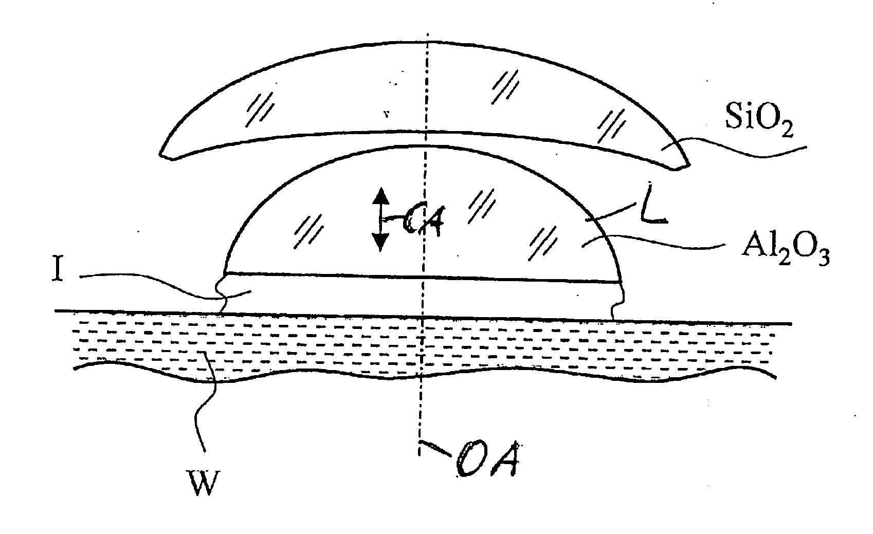
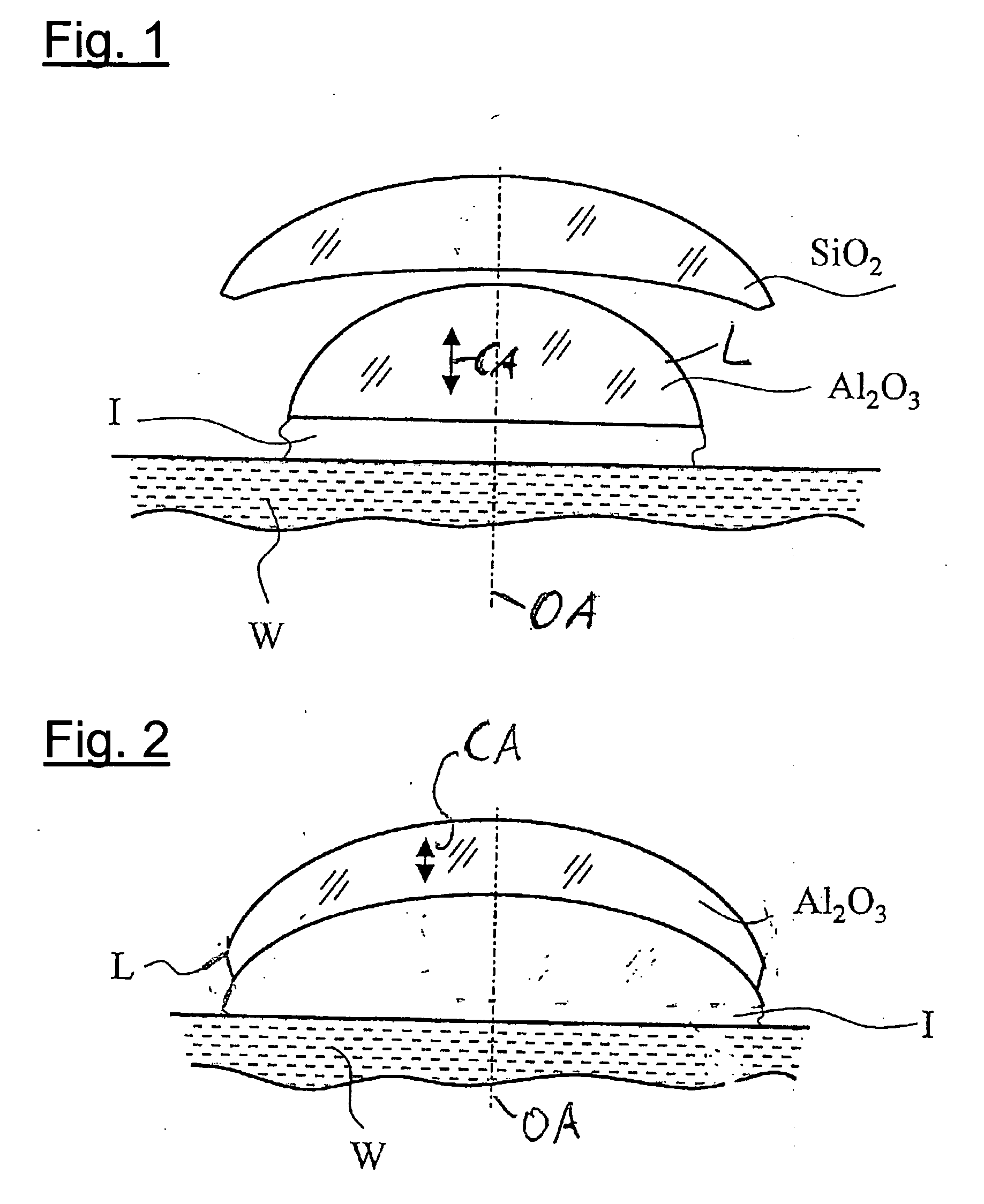
[0036]FIG. 1 diagrammatically shows an embodiment by way of example with a planoconvex lens L (of sapphire) with planar immersion I and a wafer W in the image plane. The optical axis OA of the projection objective and the crystal principal axis CA are parallel. FIG. 2 shows a variant with a meniscus lens L and similar references.

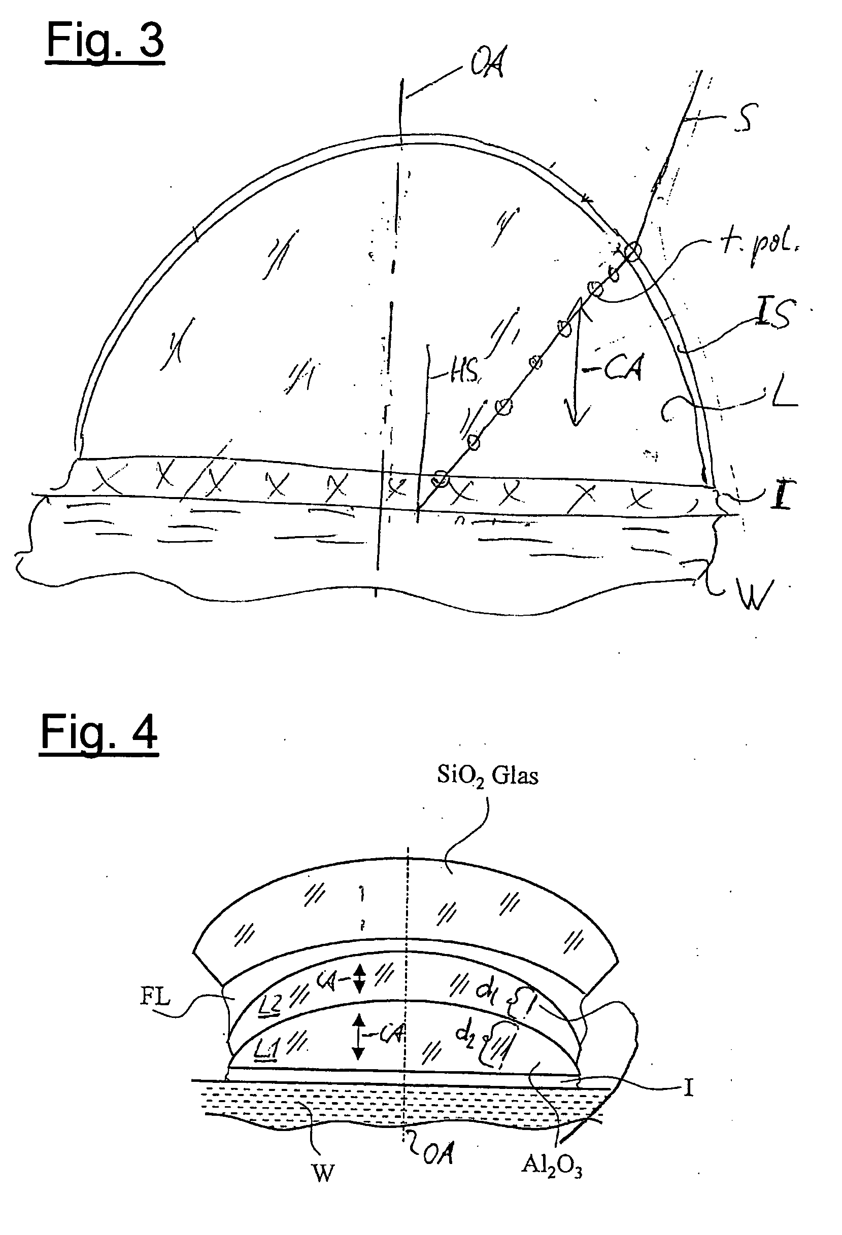
[0037] If in this respect the material of that last lens were completely isotropic, then after the last element there would be strictly tangentially polarised light, more specifically over the entire image field, although the light “etendue” is very high. What is the situation however for the conditions in the wafer or in the immersion or in the optical near field also applies exactly in the last optical element as long as, as shown above, the last optical face is almost planar or curved with an almost adapted refractive index in relation to the adjoining immersion. Tangential polarisation is also completely maintained in the last optical element, the chief...


PUM


Abstract

The invention concerns a microlithography projection objective and a microlithographic projection exposure apparatus with a microlithography projection objective, having at least one lens of birefringent material. In accordance with an aspect of the invention, a microlithography projection objective has an optical axis and at least one lens of uniaxial birefringent crystal whose principal axis is oriented parallel to the optical axis, wherein all lenses of uniaxial birefringent crystal comprise the same crystal material, wherein light is tangentially polarised in the lens of uniaxial birefringent crystal and wherein the lens of uniaxial birefringent crystal has a diffractive power different from zero and has a plane exit face or a non-plane but refractive power-less exit face.

Description

CROSS-REFERENCE TO RELATED APPLICATION [0001] This application claims priority of German Patent Application No. 10 2005 009912.2, filed Mar. 1, 2005, as well as U.S. Provisional Application 60 / 658,417, filed Mar. 2, 2005.BACKGROUND OF THE INVENTION [0002] 1. Field of the Invention [0003] The invention concerns a microlithography projection objective and a microlithographic projection exposure apparatus with a microlithography projection objective, having at least one lens of birefringent material. [0004] 2. Description of the Related Art [0005] In present microlithography objectives with working wavelengths below 365 nm, in particular 248 nm, 193 nm or 157 nm, and further in particular for immersion or near field lithography with values in respect of the numerical aperture (NA) of more than 1.0, for example 1.3 to about 2, there is increasingly a need for the use of materials with a high refractive index. Here a refractive index is referred to as being ‘high’ if its value at the spe...

Claims


Application Information

Patent Timeline
Patent Type & Authority Applications(United States)
IPC IPC(8): G02B3/00
CPCG02B1/02G02B1/08G02B5/3083G02B13/143G02B17/0816G03F7/70341G03F7/70958
Inventor SCHUSTER, KARL-HEINZ
Owner CARL ZEISS SMT GMBH
Why Eureka
Try Eureka