Dynamic appearance-changing optical devices (DACOD) printed in a shaped magnetic field including printable fresnel structures
Inactive Publication Date: 2006-09-07
VIAVI SOLUTIONS INC
View PDF99 Cites 154 Cited by
Summary
Abstract
Description
Claims
Application Information
AI Technical Summary
This helps you quickly interpret patents by identifying the three key elements:
Problems solved by technology
Method used
Benefits of technology
[0023] The flakes may be uniform in shape, and are preferabl
Problems solved by technology
Unfortunately, some optically variable devices that are intended to be noticed are not wid
Method used
Image
Click on the blue label to locate the original text in one second.
Reading with bidirectional positioning of images and text.
Examples
example 1
[0155] Multi-layered structure MgF2 / Al / Ni / Al / MgF2 was vacuum-deposited on the top of a polyester rectangular grating similar to shown in FIG. 39. The widths of the hills and the valleys of the grating were 7 microns. The height of the hills was 80 nm. The material was stripped off the embossed substrate and converted to microflakes with the average size of 24 microns.
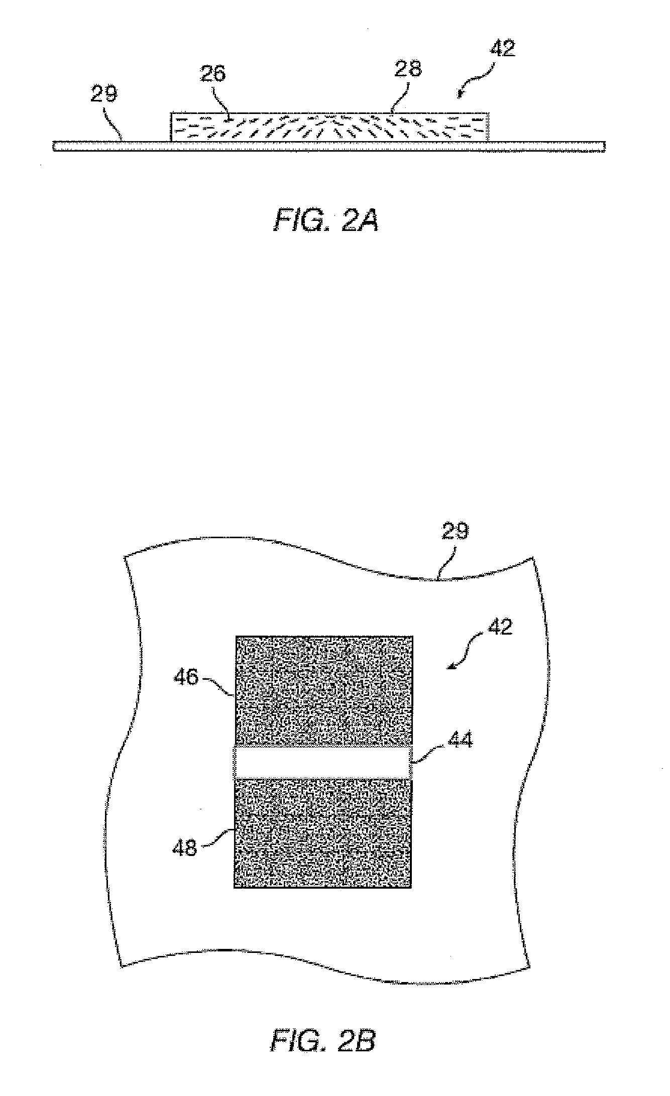
[0156] Before the MgF2 / Al / Ni / Al / MgF2 coating was stripped off the substrate, the results were compared with those of the same optical multi-layered stack deposited onto a different polyester diffractive grating having frequency of 1500 lines / mm. The color performance of the coating on both low-frequency and high-frequency substrates was characterized with the gonio-spectrophotometer (Murakami Color Research Labs). Experimental results are shown in FIG. 42.
[0157] Results in FIGS. 42a and 42b show that the sample of low-modulated low-frequency rectangular grating generates barely visible diffractive colors when measurem...
PUM
Property
Measurement
Unit
Fraction
aaaaa
aaaaa
Thickness
aaaaa
aaaaa
Thickness
aaaaa
aaaaa
Abstract
A printed image is disclosed wherein the image may be in the form of an array of magnetically aligned platelets or flakes that may by uniform in shape and size and wherein the flakes are arranged in a particularly manner to form optically illusive images useful as security devices, or useful in beam steering applications. In one embodiment of this invention printed array is disclosed a plurality of concentric rings of magnetically aligned platelets disposed upon a substrate in the form of a Fresnel structure, preferably a Fresnel reflector. Advantageously, since the magnetic field can be controlled with respect to strength and direction, one can easily design a field that will correct for spherical aberration that would otherwise be present in a typical Fresnel reflector. In other embodiments of the invention optically illusive images of funnels, domes and cones are printed.
Description
CROSS-REFERENCE TO RELATED APPLICATIONS [0001] The present application is a continuation-in-part of U.S. patent application Ser. No. 11 / 313,165 filed Dec. 20, 2005, which is a continuation-in-part of U.S. patent application Ser. No. 11 / 022,106, filed Dec. 22, 2004, which is a continuation-in-part from U.S. patent application Ser. No. 10 / 386,894 filed Mar. 11, 2003, which claims priority from U.S. Provisional Patent Application Ser. No. 60 / 410,546 filed Sep. 13, 2002; from U.S. Provisional Patent Application Ser. No. 60 / 410,547 filed Sep. 13, 2002; from U.S. Provisional Patent Application Ser. No. 60 / 396,210 filed Jul. 15, 2002 by the disclosures of which are hereby incorporated in their entirety for all purposes; and the present application is a continuation-in-part of U.S. patent application Ser. No. 11 / 028,819 filed Jan. 4, 2005 which is a continuation-in-part of U.S. patent application Ser. No. 10 / 243,111 filed Sep. 13, 2002, issued as U.S. Pat. No. 6,902,807 on Jun. 7, 2005 by t...
Claims
Application Information
Patent Timeline
Application Date:The date an application was filed.
Publication Date:The date a patent or application was officially published.
First Publication Date:The earliest publication date of a patent with the same application number.
Issue Date:Publication date of the patent grant document.
PCT Entry Date:The Entry date of PCT National Phase.
Estimated Expiry Date:The statutory expiry date of a patent right according to the Patent Law, and it is the longest term of protection that the patent right can achieve without the termination of the patent right due to other reasons(Term extension factor has been taken into account ).
Invalid Date:Actual expiry date is based on effective date or publication date of legal transaction data of invalid patent.