

Torque vectoring device having an electric motor/brake actuator and friction clutch
- Summary
- Abstract
- Description
- Claims
- Application Information
AI Technical Summary
Benefits of technology
Problems solved by technology
Method used
Image

Examples
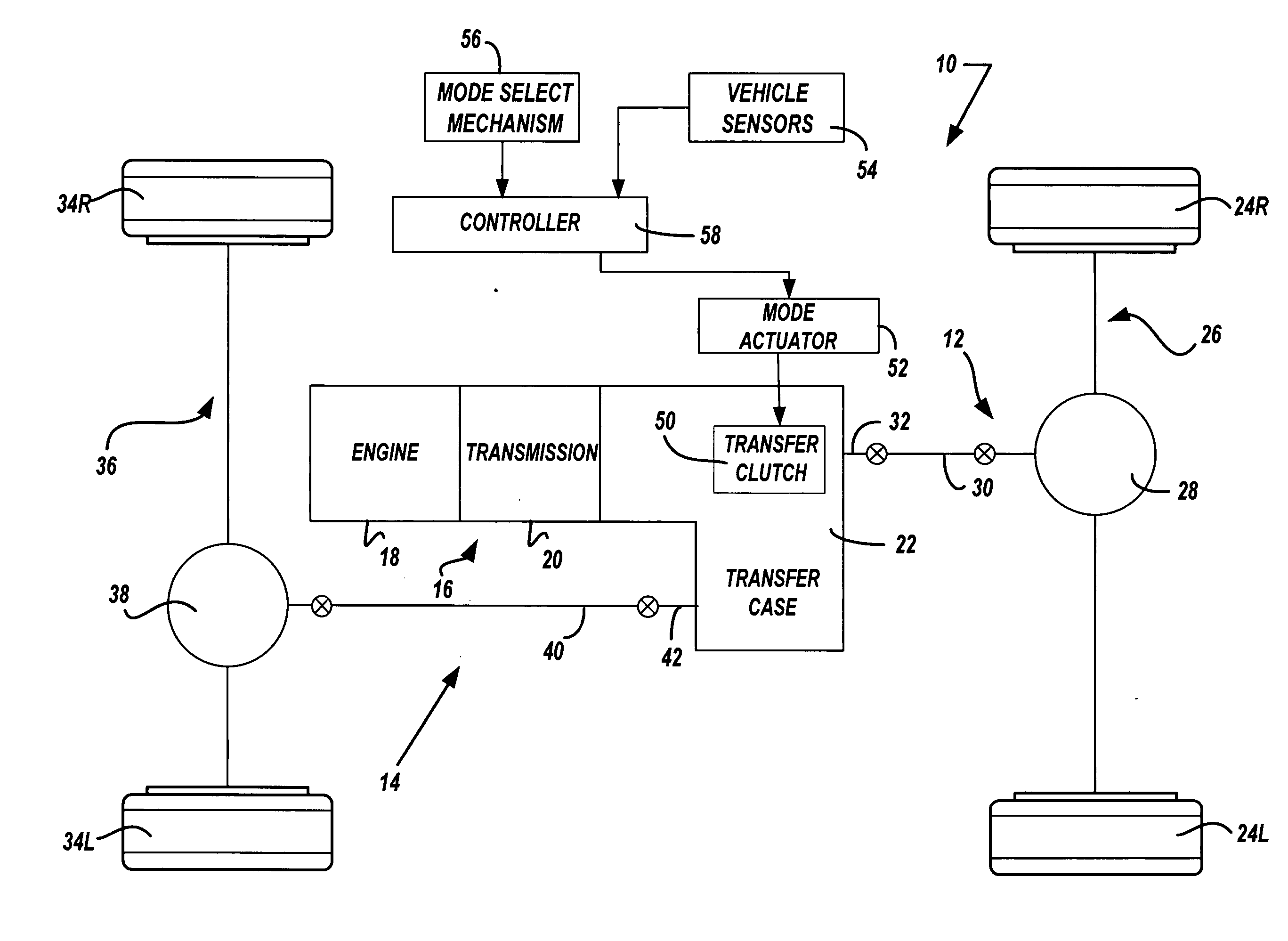
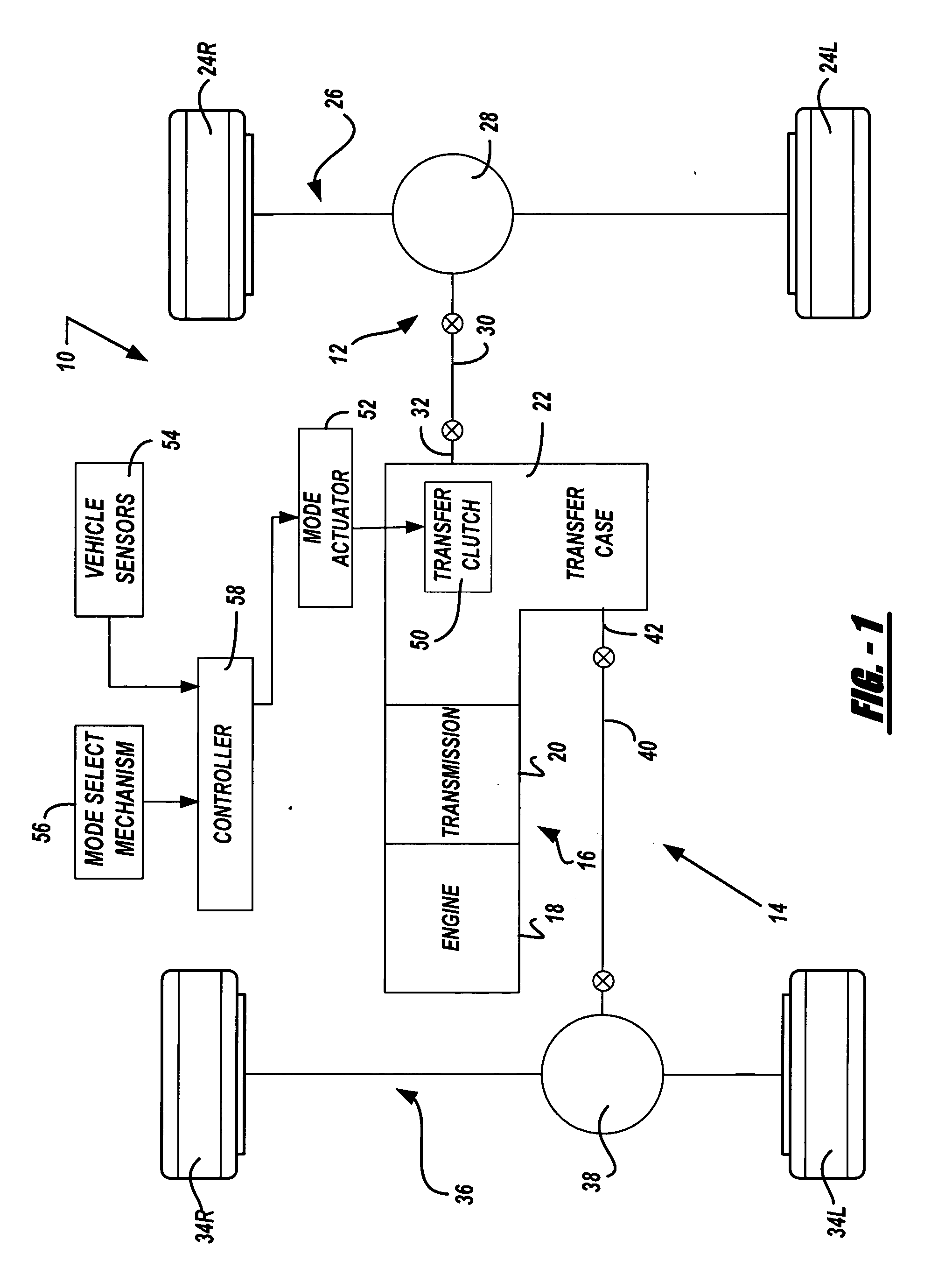
case 22
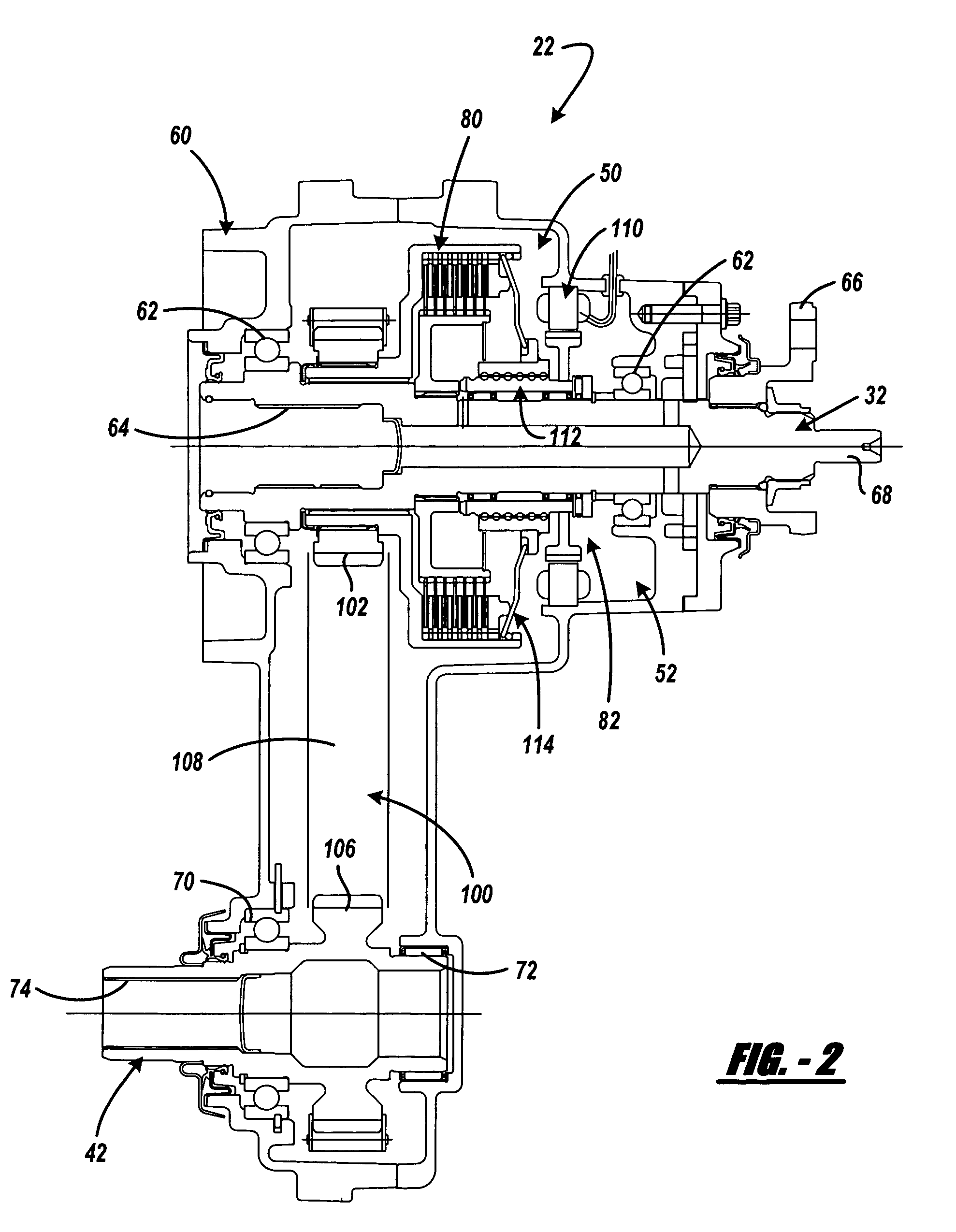
[0041] Transfer case 22 is shown in FIG. 2 to include a multi-piece housing 60 from which rear output shaft 32 is rotatably supported by a pair of laterally-spaced bearing assemblies 62. Rear output shaft 32 includes an internally-splined first end segment 64 adapted for connection to the output shaft of transmission 20 and a yoke assembly 66 secured to its second end segment 68 that is adapted for connection to rear propshaft 30. Front output shaft 42 is likewise rotatably supported from housing 60 by a pair of laterally-spaced bearing assemblies 70 and 72 and includes an internally-splined end segment 74 that is adapted for connection to front propshaft 40.
[0042] Transfer clutch 50 is a multi-plate friction clutch assembly 80 and mode actuator 52 is a power-operated clutch actuator assembly 82 which together define a torque transfer mechanism according to a preferred embodiment of the present invention. Friction clutch assembly 80 includes a hub 84 fixed via a spline connection 86...
PUM
 Abstract
Description
Claims
Application Information