Storage system

a storage system and storage technology, applied in the field of storage systems, can solve the problems of limiting data transmission capability among clusters, increasing the cost of small scale storage systems, and limited storage system scale to be constructed, so as to achieve the effect of reducing data transmission path uniformity, enhancing fault tolerance, and reducing cos

Inactive Publication Date: 2006-09-07
HITACHI LTD
View PDF9 Cites 30 Cited by
  • Summary
  • Abstract
  • Description
  • Claims
  • Application Information

AI Technical Summary

Benefits of technology

[0016] According to the aspect of the invention, an arbitrary scale storage system can be constructed at proper cost according to a scale, without limits. Further, according to the invention, performance ununiformity due to a data transmission path is relieved. In addition, according to the invention, since there are many data transmission paths, fault tolerance is enhanced.

Problems solved by technology

According to the crossbar switching network, the scale of the storage system to be constructed is limited by the scale of the switch.
If the large scale switch is used in the small scale storage system, the cost of the small scale storage system increases.
However, in order to suppress the cost increase of the switch, there is no choice but to limit data transmission capability among the clusters.
As such, in the cluster switching network, performance ununiformity occurs according to a data transmission path.
According to the completely-connected network, when the large scale storage system is constructed, lots of the connections among the switches are required, such that the configuration is complicated.
As a result, the cost of wiring lines increases and the switch becomes large.

Method used


Image

  • Storage system
  • Storage system
  • Storage system

Examples


first embodiment

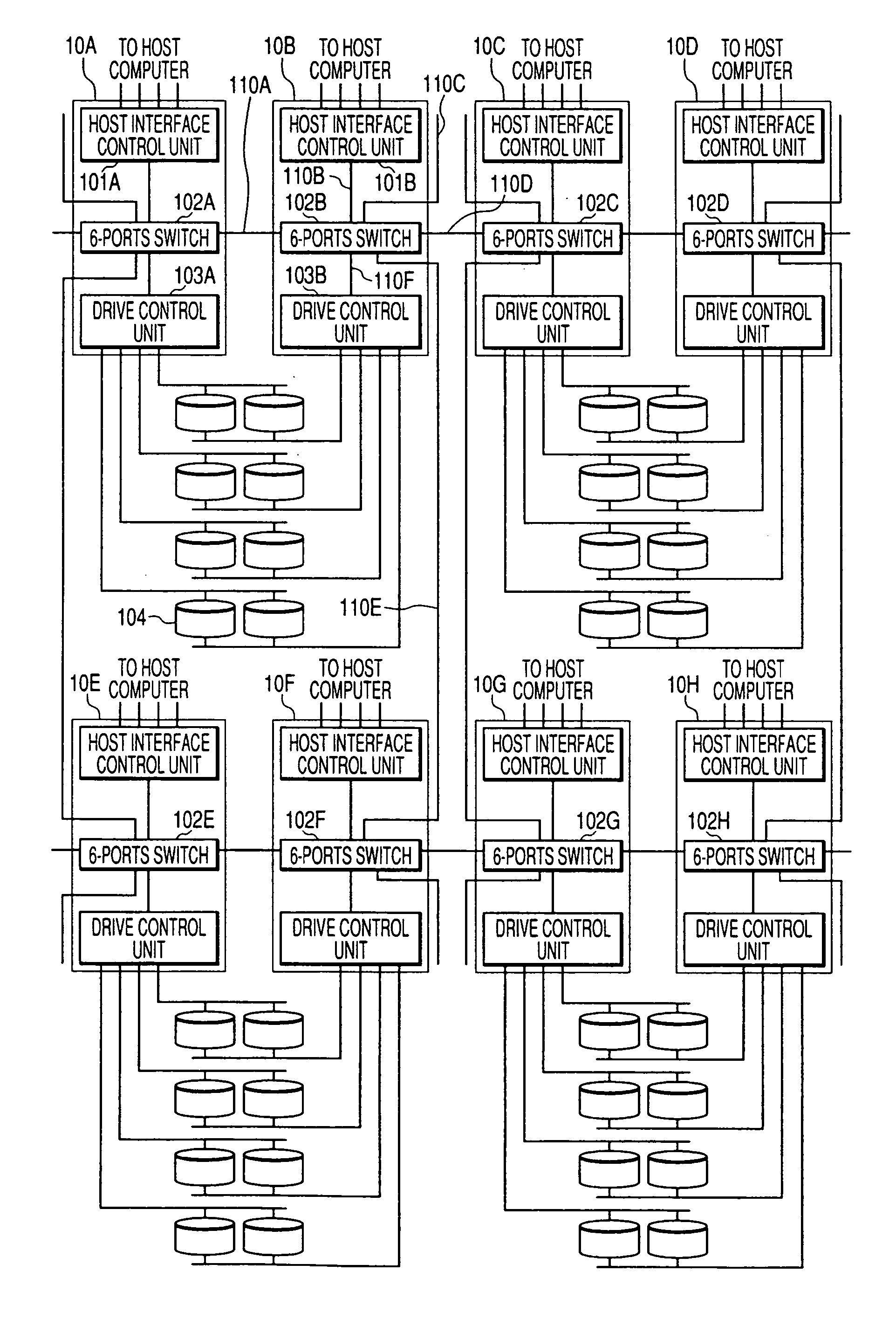
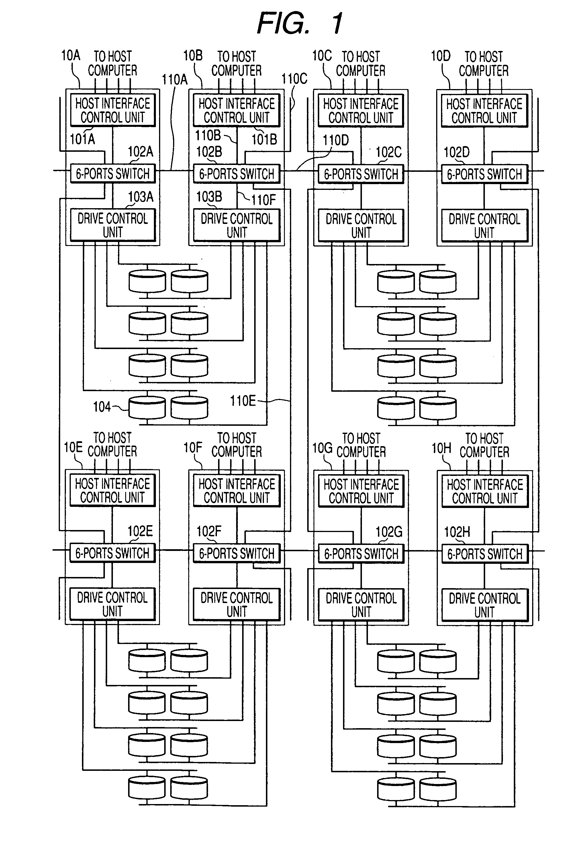
[0048]FIG. 1 is block diagram showing a configuration of a storage system according to the invention.

[0049] The storage system of the present embodiment has a plurality of storage control units 10 and a plurality of disk drives 104.

[0050] In FIG. 1, 8 storage control units 10A to 10H are shown, but the storage system of the present embodiment can include the arbitrary number of the storage control units 10.

[0051] The storage control unit 10 is connected to host computers (not shown), disk drives 104, and other storage control units 10. When receiving a request from the host computer for access to the disk drives 104, the storage control unit 10 executes the access operation. When any storage control unit 10 receives a request for access to disk drives 104 which is not connected to the storage control unit 10, the storage control unit 10 transmits the request for access to another storage control unit 10. Further, when any storage control unit 10 receives a response to a host compu...

second embodiment

[0581]FIG. 24 is a block diagram showing a configuration of a storage system according to the invention.

[0582] The storage system of the present embodiment has a plurality of storage control units 2400 and a plurality of disk drives 104.

[0583] The storage control unit 2400 is the same as the storage control unit 10 of the first embodiment of the invention (see FIG. 1), except that it has an 8-ports switch 2401, instead of the 6-ports switch 102. Then, in the present embodiment, the descriptions of the same portions as those of the first embodiment of the invention will be omitted.

[0584] In FIG. 24, 8 storage control units 2400A to 2400H are shown, but the storage system of the present embodiment can have the arbitrary number of storage control units 2400.

[0585] The storage control unit 2400 has a host interface control unit 101, an 8-ports switch 2401, and a drive control unit 103.

[0586] The 8-ports switch 2401 is connected to the host interface control unit 101 in the same stor...

third embodiment

[0610]FIG. 25 is a block diagram showing a configuration of a storage system according to the invention.

[0611] The storage system of the present embodiment has a plurality of storage control units 2500 and a plurality of disk drives 104.

[0612] The storage control unit 2500 is the same as the storage control unit 10 of the first embodiment of the invention (see FIG. 1), except that it has a 10-ports switch 2501, instead of the 6-ports switch 102. Then, in the present embodiment, the descriptions of the same portions as those of the first embodiment of the invention will be omitted.

[0613] In FIG. 25, 8 storage control units 2500A to 2500H are shown, but the storage system of the present embodiment can have the arbitrary number of storage control units 2500.

[0614] The storage control unit 2500 has a host interface control unit 101, a 10-ports switch 2501, and a drive control unit 103.

[0615] The 10-ports switch 2501 is connected to the host interface control unit 101 in the same sto...


PUM


Abstract

There is provided architecture of a storage system, which has high scalability, low performance ununiformity, and strong fault tolerance, and a control method thereof. The storage system is connected to a host computer. The storage system has four or more nodes. Each node has a host interface unit which is connected to the host computer to communicate with the host computer, and a switch which communicates with the host interface unit. The switch is connected to the switches of other four or less nodes to communicate with the switches of other nodes, such that the nodes are connected to one another in a two-dimensional lattice shape.

Description

CROSS-REFERENCES TO RELATED APPLICATIONS [0001] This application relates to and claims priority from Japanese Patent Application No. 2005-056470, filed on Mar. 1, 2005, the entire disclosure of which is incorporated herein by reference. BACKGROUND OF THE INVENTION [0002] 1. Field of the Invention [0003] The present invention relates to a storage system which can enhance scalability and fault tolerance. [0004] 2. Description of the Related Art [0005] In the current data storage system market, very large scale storage systems to which a plurality of host computers are connected are demanded. For example, for the use in a data center of a large company or the like, the large scale storage system having high performance and reliability are demanded. [0006] On the other hand, with the spread of the open systems market, demands for small scale storage systems which have the same performance and reliability as those of the large scale storage systems are increasing. [0007] In order to meet...

Claims


Application Information

Patent Timeline
Patent Type & Authority Applications(United States)
IPC IPC(8): G06F11/00
CPCG06F3/0617G06F3/0635G06F3/0683G06F11/2007G06F11/201G06F11/2053H04L49/1507H04L67/1097
Inventor SHIMADA, KENTARO
Owner HITACHI LTD
Why Eureka
Try Eureka