Electromagnetic drive mechanism and a high-pressure fuel supply pump

a drive mechanism and drive shaft technology, applied in the direction of fuel injection pumps, electric control, machines/engines, etc., can solve the problems of increasing configuration costs and creating individual differences, and achieve the effect of increasing costs

Active Publication Date: 2006-09-14
HITACHI ASTEMO LTD
View PDF12 Cites 24 Cited by
  • Summary
  • Abstract
  • Description
  • Claims
  • Application Information

AI Technical Summary

Benefits of technology

[0007] However, this configuration will increase cost and may create an individual difference depending on apparatus (difference of control characteristics among individual electromagnetic drive mechanisms) due to change over time or installation tolerance of a damping member.
[0008] The object of the-present invention is to reduce an individual difference depending on apparatus due to the change over time or installation tolerance when damping operating sounds of an electromagnetic drive mechanism used for a variable displacement control mechanism in a high-pressure fuel supply pump.
[0010] When compared to an occasion where the plunger is displaced all strokes by a magnetic biasing force, the above configuration is able to reduce the force of impact on a member (for example, valve body) mounted to the plunger and a restricting member, thereby damping the collision noise.

Problems solved by technology

However, this configuration will increase cost and may create an individual difference depending on apparatus (difference of control characteristics among individual electromagnetic drive mechanisms) due to change over time or installation tolerance of a damping member.

Method used


Image

  • Electromagnetic drive mechanism and a high-pressure fuel supply pump
  • Electromagnetic drive mechanism and a high-pressure fuel supply pump
  • Electromagnetic drive mechanism and a high-pressure fuel supply pump

Examples


embodiment 1

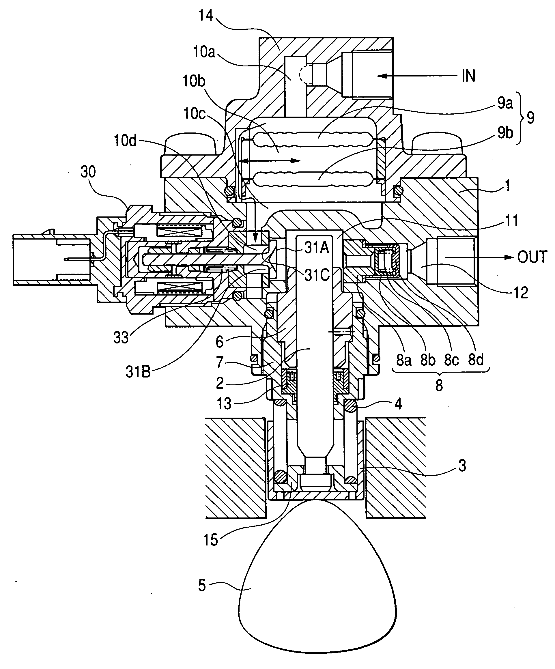
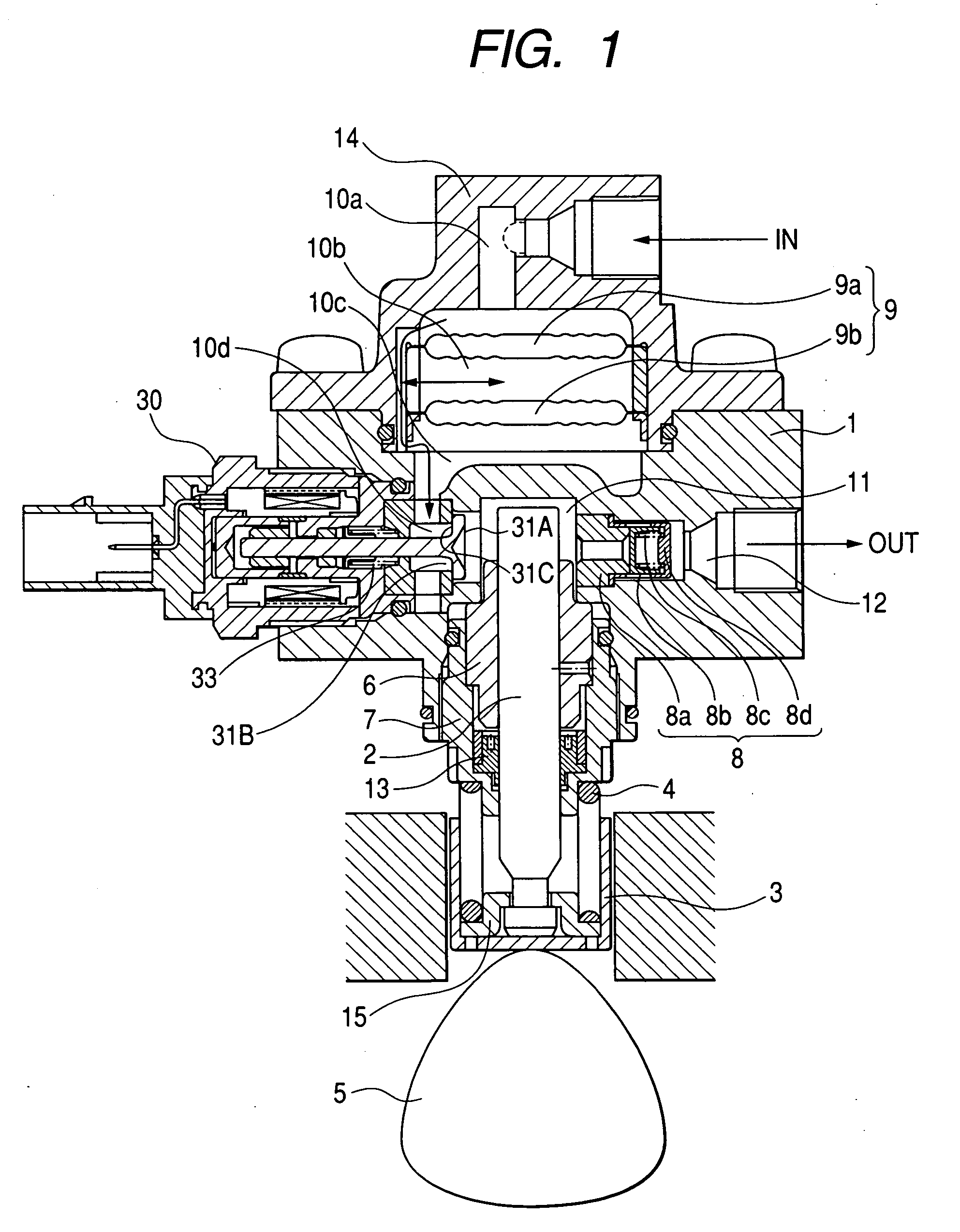
[0025]FIG. 1 is a longitudinal sectional view of an entire high-pressure fuel supply pump of a first embodiment according to the present invention.

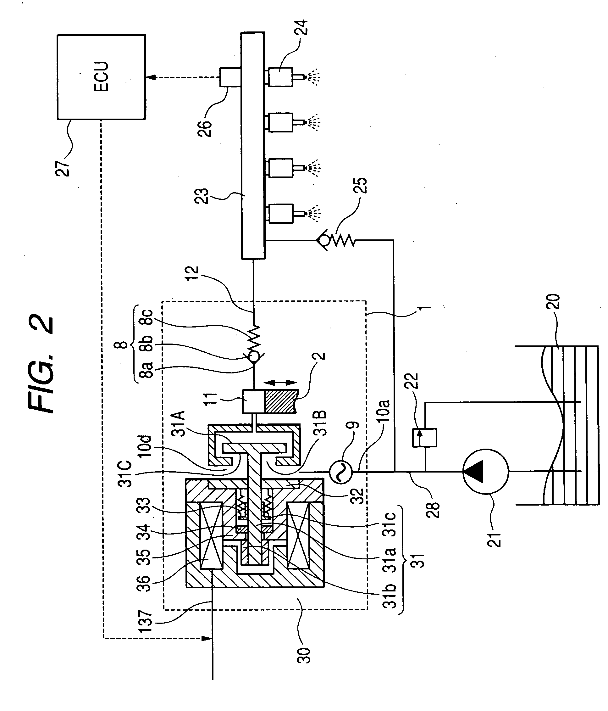
[0026]FIG. 2 is a schematic system diagram of a fuel supply system of an internal combustion engine.

[0027] A damper cover 14 including a pressure pulsation damping mechanism 9 for damping the fuel pressure pulsation is mounted to the pump body 1. The damper cover 14 has a fuel intake port 10a.

[0028] An intake passage 10 comprises fuel intake ports 10a, 10b, 10c and 10d, and a pressure pulsation damping mechanism 9 for damping the fuel pressure pulsation is located in the middle of the passage.

[0029] A fuel discharge port 12 is provided in the pump body 1, and a pressure chamber 11 for pressurizing fuel is provided in the middle of the fuel passage which extends from the fuel intake port 10ato the fuel discharge port 12.

[0030] An electromagnetic intake valve 30 is provided at the inlet of the pressure chamber 11. The electromagnetic i...

embodiment 2

[0067] Next, a second embodiment of the present invention will be described with reference to FIGS. 7 and 8.

[0068]FIG. 7 is an enlarged view of the inside of the pump. What is different from FIG. 3 and FIG. 4 is that the intake valve 31 is open but is not fully open, and does not come in contact with core 35 which is a restricting member.

[0069]FIG. 8 shows the operation of the pump. What is different from FIG. 5 is that the intake valve 31 is open but is not fully open until halfway of the intake process, and does not come in contact with core 35 which is a restricting member.

[0070] When the plunger 2 is functioning in the intake process as the result of the rotation of the cam 5, the volume of the pressure chamber 11 increases and the fuel pressure decreases. If the fuel pressure of the pressure chamber 11 becomes lower than the pressure of the intake passage 10d, a valve-opening force is generated by fluid differential pressure of fuel in the intake valve 31.

[0071] Due to the ...

embodiment 3

[0075] Next, a third embodiment of the present invention will be described with reference to FIG. 9.

[0076]FIG. 9 shows the operation of the pump. What is different from FIG. 8 is that generated current is restricted.

[0077] When the plunger 2 is functioning in the intake process as the result of the rotation of the cam 5, the volume of the pressure chamber 11 increases and the fuel pressure decreases. If the fuel pressure of the pressure chamber 11 becomes lower than the pressure of the intake passage 10d, a valve-opening force is generated by fluid differential pressure of fuel in the intake valve 31.

[0078] Due to the valve-opening force, the valve overcomes a biasing force of the intake valve spring 33 and opens. At this time, as shown in FIG. 5, it is possible to determine the necessary biasing force of the intake valve spring 33 so that the valve fully opens due to the fluid differential pressure, and comes in contact with core 35 which is a restricting member. Furthermore, it...


PUM


Abstract

The objective of the present invention is to dampen operating sounds of an electromagnetic drive mechanism used for a variable displacement control mechanism in a high-pressure fuel supply pump to reduce an individual difference depending on apparatus due to the change over time or installation tolerance. To achieve the above objective, the present invention is configured such that before the electromagnetic drive mechanism supplies a drive force to a plunger which is electromagnetically driven by the electromagnetic drive mechanism, another displacement force situates the plunger in a specific position. When compared to an occasion where the plunger is displaced all strokes by a magnetic biasing force, the above configuration is able to reduce the force of impact on a member (for example, valve body) mounted to the plunger and a restricting member, thereby damping the collision noise. Furthermore, since an extra member, such as a damping member, is not required, individual difference depending on apparatus do not easily occur.

Description

CLAIM OF PRIORITY [0001] The present application claims priority from Japanese application serial No. 2005-069668, filed on Mar. 11, 2005, the contents of which is hereby incorporated by references into this application. BACKGROUND OF THE INVENTION [0002] 1. Field of the Invention [0003] The present invention relates to an electromagnetic drive mechanism, and specifically to a high-pressure fuel supply pump for an internal combustion engine that uses this kind of electromagnetic drive mechanism. [0004] 2. Description of Related Art [0005] In a high-pressure fuel supply pump comprising a variable displacement mechanism that includes an electromagnetic drive mechanism described in Japanese Application Patent Laid-Open Publication No. 2002-250462, a damping alloy is provided in a restriction part for restricting the movement of a movable member in order to dampen operating sounds of a variable displacement control mechanism including an electromagnetic drive mechanism. [0006] [Patent D...

Claims


Application Information

Patent Timeline
Patent Type & Authority Applications(United States)
IPC IPC(8): F02M59/36
CPCF02D41/20F02D2041/2027F02D2041/2058F02M59/102F02M59/367F02M2200/315F02M63/0035F02M63/0225F02M63/024F02M2200/09F02M63/0017
Inventor USUI, SATOSHITOKUO, KENICHIROYAMADA, HIROYUKIABE, MASAMIODAKURA, HIROSHI
Owner HITACHI ASTEMO LTD
Why Eureka
Try Eureka