Battery box assembly

Inactive Publication Date: 2006-09-14
MASCO CORP
View PDF20 Cites 68 Cited by
  • Summary
  • Abstract
  • Description
  • Claims
  • Application Information

AI Technical Summary

Benefits of technology

[0003] The present invention generally relates to compartments for housing batteries, and more particularly to a bat

Problems solved by technology

Many conventional battery compartments are difficult to access, particularly when the electronics are installed such that they are not visible in ordinary circumstances.
When a conventional battery compartment is used and the batteries hous

Method used


Image

  • Battery box assembly
  • Battery box assembly
  • Battery box assembly

Examples


Embodiment Construction

[0022] The embodiments described below are merely exemplary and are not intended to limit the invention to the precise forms disclosed. Instead, the embodiments were selected for description to enable one of ordinary skill in the art to practice the invention.

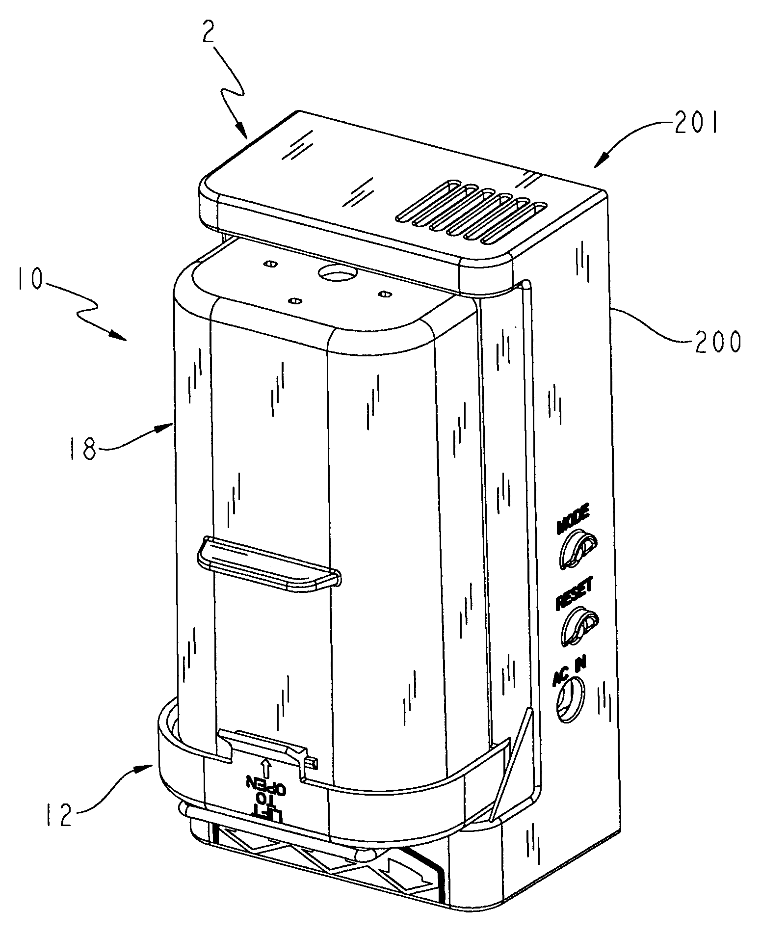
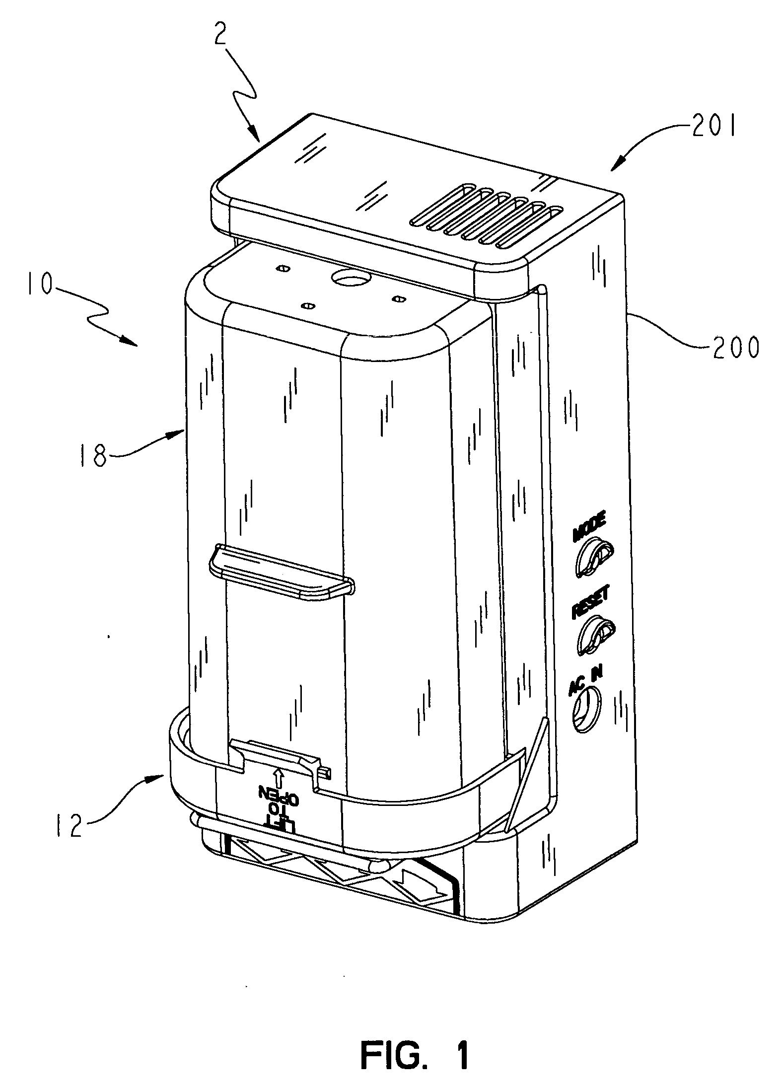
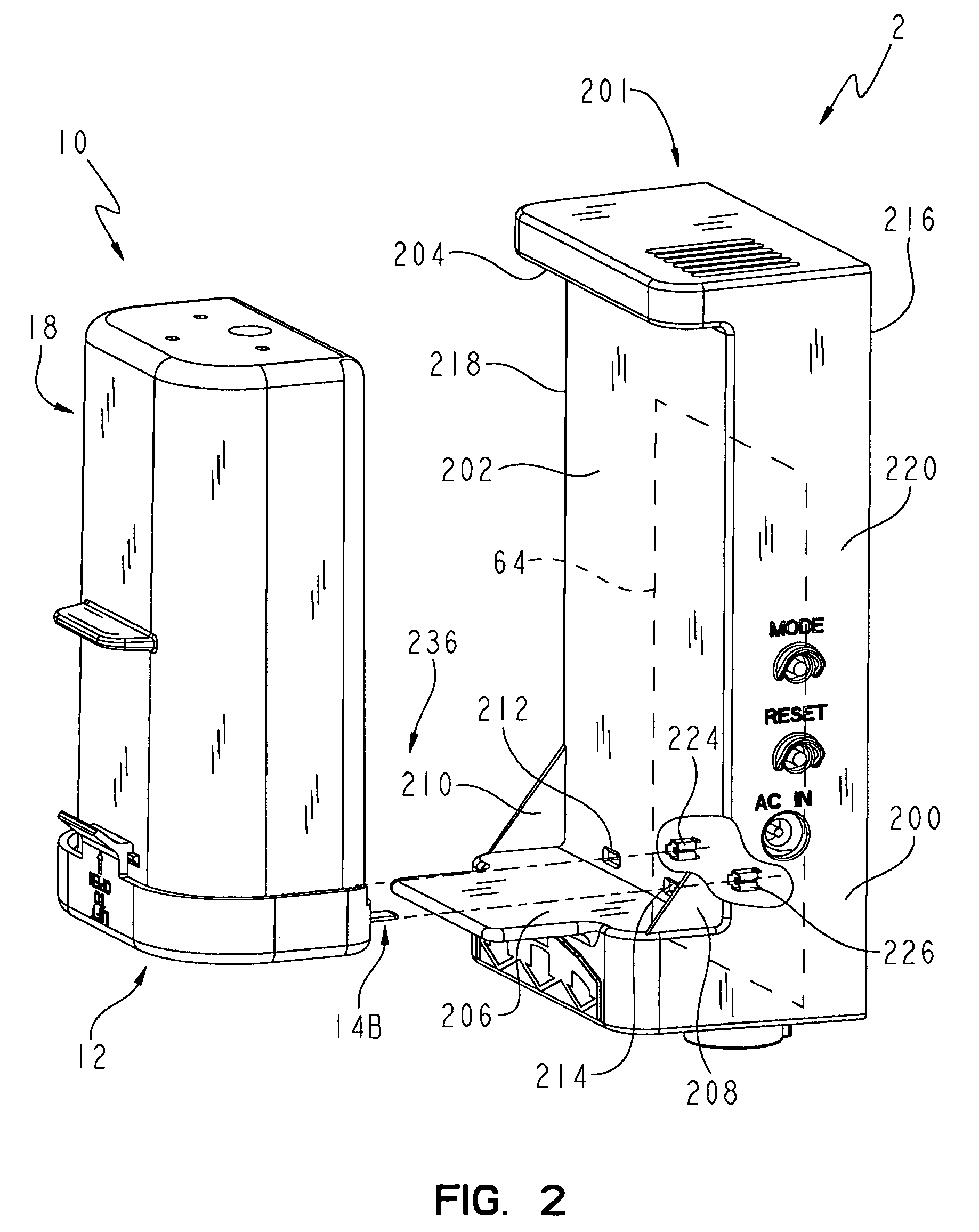
[0023] Referring initially to FIGS. 1 and 2, a controller assembly 2 illustratively includes a battery compartment 10 operably coupled to a control unit 201. Battery compartment 10 according to one embodiment of the present invention generally includes a lid 12, a first contact 14A, a second contact 14B, a spring 16, and a housing 18 (FIG. 5). As best shown in FIGS. 4, 5, 10, and 11, lid 12, which is formed of a non-conductive material, includes an upper wall 20 and a side wall 22 which together substantially define an interior space 24. Upper wall 20 includes four pins 26A-26D that are spaced and sized to secure contacts 14A, 14B to lid 12 as is further described below. Side wall 22 extends about the perimeter of the upper wa...


PUM


Abstract

A battery compartment assembly includes a housing and a lid configured to be removably attached to the housing. The lid includes a pair of hinges that engage a corresponding pair of openings in the housing, and a latch that engages a ridge on the housing when the lid is in the closed position. The lid also includes a pair of contacts that extend from the lid to mate with connectors of a control unit to be powered by the batteries in the assembly. A spring is included in the housing for connecting to a positive terminal of a first battery and a negative terminal of a second battery.

Description

CROSS-REFERENCE TO RELATED APPLICATIONS [0001] This application claims the benefit of U.S. Provisional Application No. 60 / 661,981, filed Mar. 14, 2005, which is expressly incorporated by reference herein. [0002] This application also expressly incorporates by reference the disclosure of each of the following applications: (1) U.S. patent application Ser. No. 10 / 755,581, filed Jan. 12, 2004, titled “MULTI-MODE HANDS FREE AUTOMATIC FAUCET,” (2) U.S. patent application Ser. No. 10 / 755,582, filed Jan. 12, 2004, titled “CONTROL ARRANGEMENT FOR AN AUTOMATIC RESIDENTIAL FAUCET,” (3) U.S. patent application Ser. No. 10,757,316, filed Jan. 14, 2004, now U.S. Pat. No. 6,962,168, titled “CAPACITIVE TOUCH ON / OFF CONTROL FOR AN AUTOMATIC RESIDENTIAL FAUCET,” (4) U.S. patent application Ser. No. 10 / 912,254, filed Aug. 5, 2004, now U.S. Pat. No. 6,968,860, titled “RESTRICTED FLOW HANDS-FREE FAUCET,” (5) U.S. Provisional Patent Application Ser. No. 60 / 661,982, filed Mar. 14, 2005, titled “POSITION-...

Claims


Application Information

Patent Timeline
IPC IPC(8): G05D16/06H01M50/213H01M50/271H01M50/296
CPCE03C1/055H01M2/1022H01M2/105H01M2/1055Y10T137/87917Y02E60/10H01M50/213H01M50/296H01M50/271
Inventor MARTY, GARRY ROBINSAILORS, TIMOTHY JAY JR.MOORE, JEFFREY LEE
Owner MASCO CORP
Why Eureka
Try Eureka