Vehicle roof structure

a technology for roof supports and vehicles, applied in the direction of roofs, transportation and packaging, vehicle arrangements, etc., can solve the problems of weak point in the overall strength and rigidity and the increase of manufacturing costs of fasteners, so as to improve the strength of the roof support structure and reduce manufacturing costs

Inactive Publication Date: 2006-09-14
NISSAN MOTOR CO LTD
View PDF22 Cites 29 Cited by
  • Summary
  • Abstract
  • Description
  • Claims
  • Application Information

AI Technical Summary

Benefits of technology

[0008] It has been discovered that in the construction and manufacture of a roof support structure in a vehicle, structural design changes can improve the strength of the roof support structure and reduce manufacturing costs.

Problems solved by technology

Typically, such threaded apertures can be a weak point in the overall strength and rigidity of the roof support structure.
The fastener connection also increases manufacturing costs.

Method used


Image

  • Vehicle roof structure
  • Vehicle roof structure
  • Vehicle roof structure

Examples


Embodiment Construction

[0040] Selected embodiments of the present invention will now be explained with reference to the drawings. It will be apparent to those skilled in the art from this disclosure that the following descriptions of the embodiments of the present invention are provided for illustration only and not for the purpose of limiting the invention as defined by the appended claims and their equivalents.

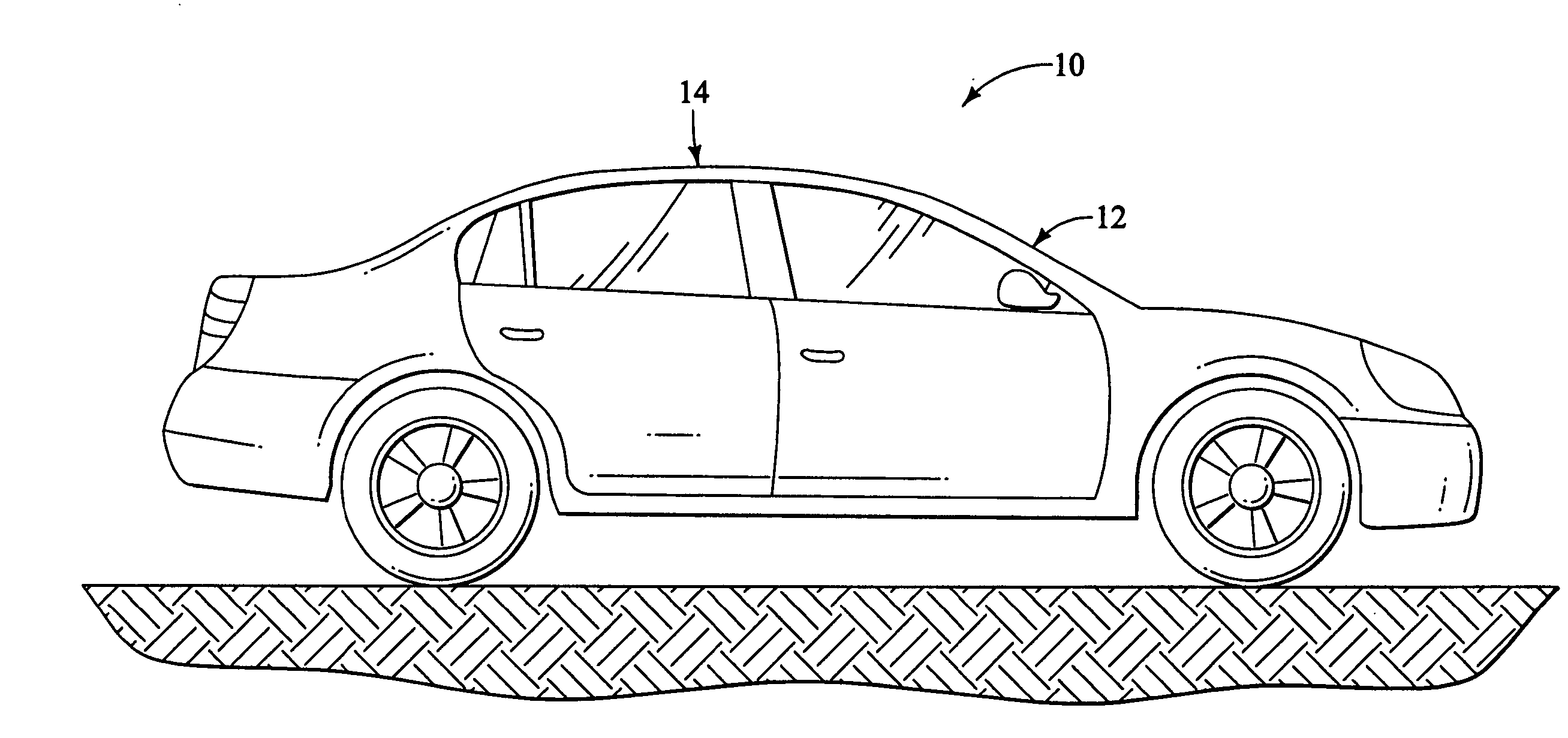
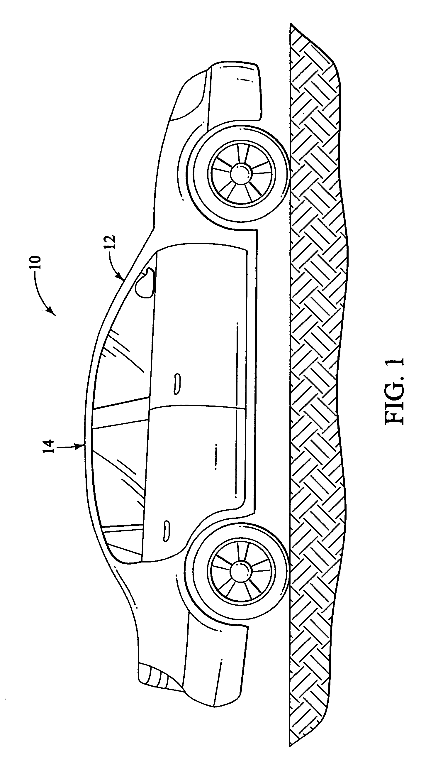
[0041] Referring initially to FIG. 1, a vehicle 10 is illustrated that is equipped with a roof support structure 12 in accordance with a first embodiment of the present invention. The roof support structure 12 of the present invention provides improved strength and rigidity in offset deformable barrier tests (ODB) as compared to conventional roof support structures, as will be apparent to those skilled in the art from the drawings and description below. It should be understood that portions of the vehicle 10 that assist in understanding the present invention are described below. However, descript...


PUM


Abstract

A vehicle roof structure is disclosed that includes a front roof rail, a pair of front roof rail braces and a pair of A-pillars. First ends of the front roof rail braces are fixedly coupled to opposite ends of the front roof rail. The pair of A-pillars each has an inner A-pillar panel. Second ends of the front roof rail braces are bonded to a connection area of a respective one of the inner A-pillar panels such that the opposite ends of the front roof rail are spaced inwardly from the inner A-pillar panels by the front roof rail braces. The front roof rail extends perpendicularly from the A-pillars via the front roof rail braces. Further, each of the inner A-pillar panels has a generally constant overall transverse cross sectional shape across the connection areas of the inner A-pillar panels.

Description

BACKGROUND OF THE INVENTION [0001] 1. Field of the Invention [0002] The present invention generally relates to a vehicle roof structure. More specifically, the present invention relates to a connection area of a vehicle roof structure that is formed between a front roof rail brace and A-pillar bonded. [0003] 2. Background Information [0004] Many vehicles utilize a conventional unitized (self-supporting) vehicle body that is built from hollow sheet metal components onto which body panels are welded. Generally, the structural configurations of these unitized vehicle bodies are continuously being improved for a variety of reasons. For instance, these unitized vehicle bodies have been developed so as to simplify the assembly process, and thereby reducing manufacturing costs. Moreover, these unitized vehicle bodies have been extensively redesigned over the years to make the vehicles safer in order to protect passengers in the event of an accident. [0005] It is therefore important for a v...

Claims


Application Information

Patent Timeline
Patent Type & Authority Applications(United States)
IPC IPC(8): B60J7/00B60R99/00
CPCB62D25/02B62D25/06
Inventor OSTERBERG, GARY R.BLANCHARD, ROBERT R.
Owner NISSAN MOTOR CO LTD
Why Eureka
Try Eureka