Magnetic encoder and signal processing circuit for the magnetic encoder

a signal processing circuit and encoder technology, applied in the direction of magnetic measurement, instruments, measurement devices, etc., can solve the problems of easy contact between the magnetic sensor element and the magnetic medium, no magnetic field signal will be provided to a location, and error in position detection,

Inactive Publication Date: 2006-09-14
TDK CORPARATION
View PDF5 Cites 10 Cited by
  • Summary
  • Abstract
  • Description
  • Claims
  • Application Information

AI Technical Summary

Benefits of technology

[0024] It is preferred that each magnetic sensor element is at least one MR element. In this case, the at least one MR element

Problems solved by technology

However, the narrower the magnetized pitch of the magnetic medium, the more cancellation of the magnetic field between the neighbor magnetized parts of the magnetic medium occurs, and thus no magnetic field signal will be provided to a location far from the magnetic medium surface.
Also, when a separation distance or gap distance between the magnetic medium and the magnetic sensor element slightly increases, the detection signal from the magnetic sensor element abruptly decreases causing an error in position detection to occur.
However, the narrower the gap distance between the magnetic sensor element

Method used


Image

  • Magnetic encoder and signal processing circuit for the magnetic encoder
  • Magnetic encoder and signal processing circuit for the magnetic encoder
  • Magnetic encoder and signal processing circuit for the magnetic encoder

Examples


Embodiment Construction

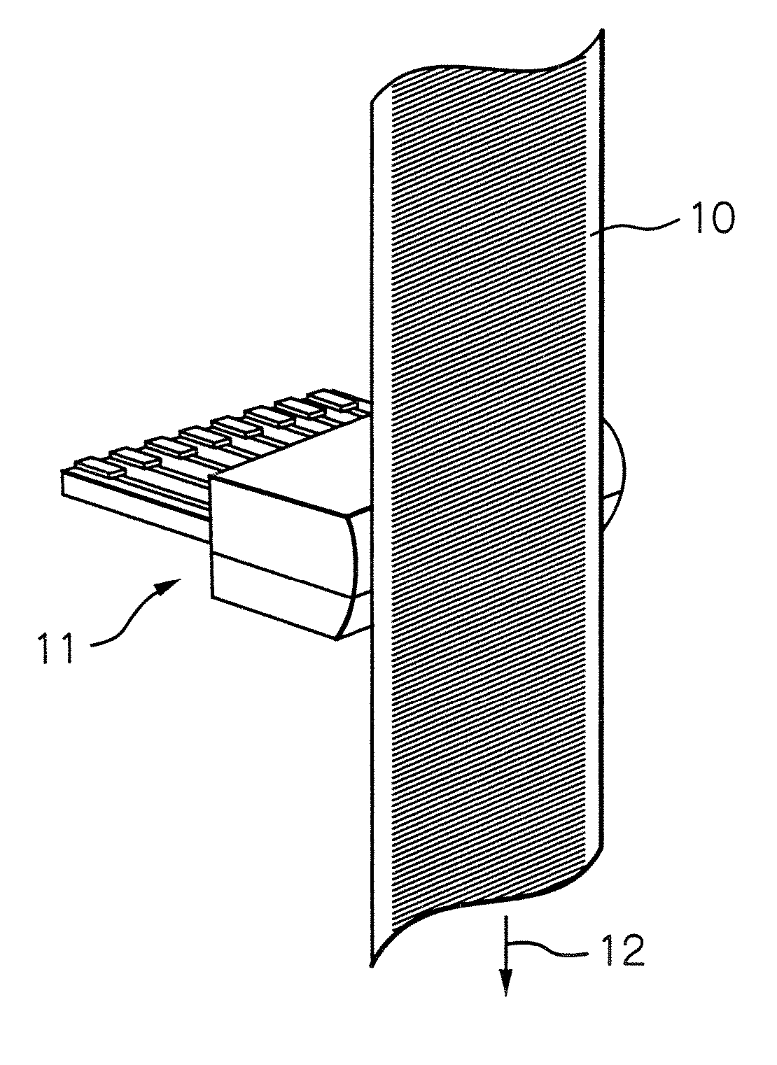
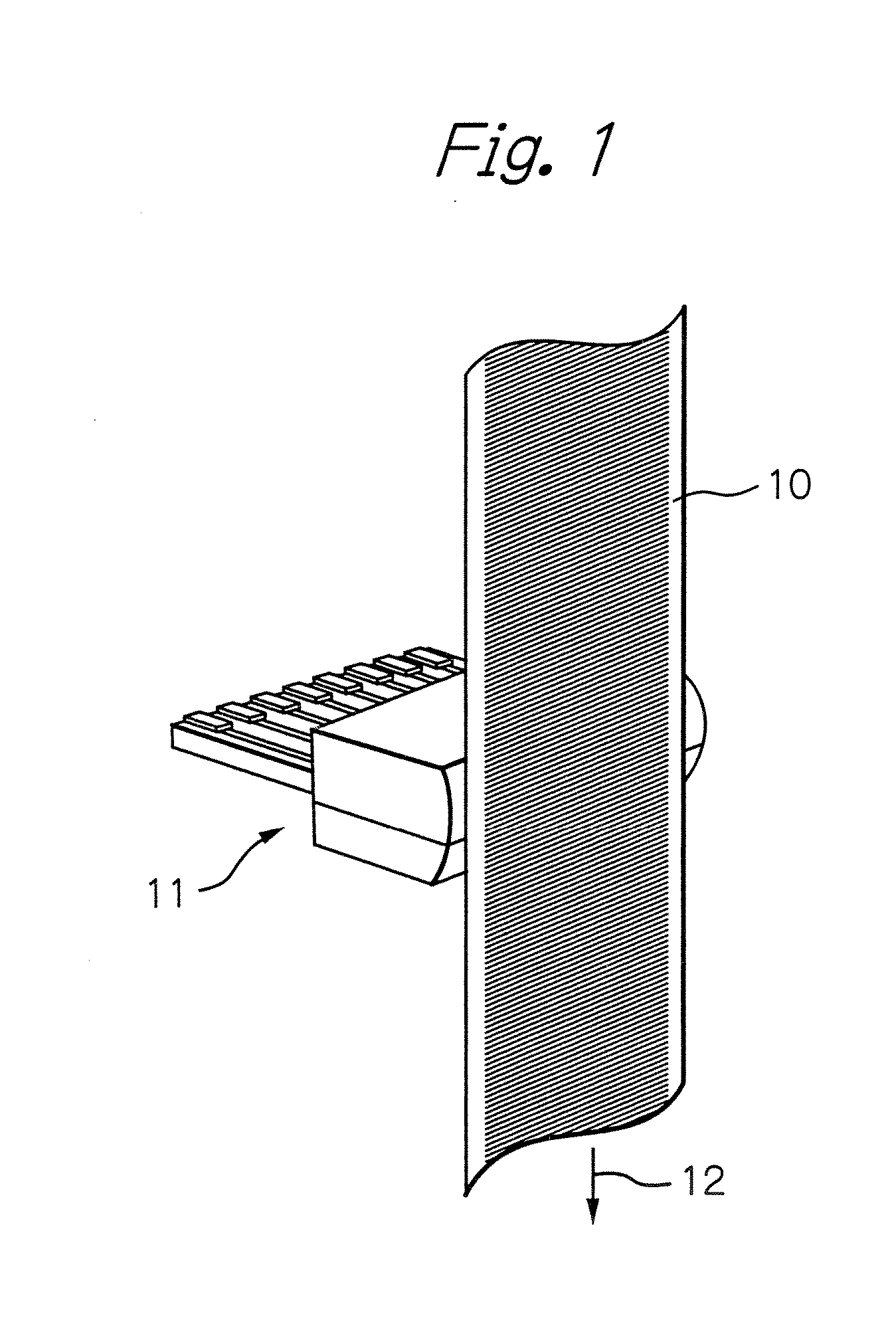
[0036]FIG. 1 schematically illustrates a configuration of a magnetic encoder as a preferred embodiment according to the present invention.

[0037] In the figure, reference numeral 10 denotes a magnetic medium to which a magnetic pattern with a predetermined magnetized pitch λ is recorded, and 11 denotes a magnetic sensor assembly with a sliding surface faced to and kept close to the magnetic medium 10, respectively.

[0038] In this embodiment, the magnetic medium 10 is fixed to a surface of an object (not shown) of which position or angle and movement directions or rotation directions are to be detected. During operation, the magnetic sensor assembly 11 is held at rest with keeping close to the surface of the magnetic medium 10. The magnetic medium 10 relatively moves with respect to the magnetic sensor assembly 11 in a direction and / or the opposite direction of an arrow 12. As for the magnetic medium, any configuration such as a flat-shaped magnetic medium, a rotating drum-shaped mag...


PUM


Abstract

A magnetic encoder includes a magnetic medium, at least three magnetic sensor elements opposed to the magnetic medium and sequentially arranged within a range equal to or shorter than a magnetized pitch or magnetized pitches of the magnetic medium, along a relative movement direction with respect to the magnetic medium, and a signal processing circuit receiving output signals from the at least three magnetic sensor elements. The signal processing circuit includes an input unit for detecting logical states of the output signals received from the at least three magnetic sensor elements and for generating a sequence of state-detection signals arranged in the order of the at least three magnetic sensor elements, and a judgment unit for judging that the output signals received are correct output signals only when the state-detection signal sequence generated agrees with either of two expected state-detection signal sequences.

Description

PRIORITY CLAIM [0001] This application claims priority from Japanese patent application No. 2005-065165, filed on Mar. 9, 2005, which is incorporated herein by reference. BACKGROUND OF THE INVENTION [0002] 1. Field of the Invention [0003] The present invention relates to a magnetic encoder provided with three or more magnetic sensor elements and to a signal processing circuit for the magnetic encoder. [0004] 2. Description of the Related Art [0005] Japanese patent publication No. 10-160511A discloses a typical magnetic encoder used for position detection, displacement detection or rotation detection. This encoder has a magnetic medium with a certain magnetization pattern formed by the horizontal magnetization recording method, and a magnetic sensor with magnetoresistive effect (MR) elements each having a sensing plane in parallel with the surface of the magnetic medium to sense a plane direction or horizontal direction component of the horizontally recorded magnetic field from the m...

Claims


Application Information

Patent Timeline
IPC IPC(8): G01B7/14
CPCG01D5/145G01D5/24495G01D5/24461
Inventor SHOJI, SHIGERU
Owner TDK CORPARATION
Why Eureka
Try Eureka