Oscillator with acoustic surface wave resonators

a surface wave and oscillator technology, applied in the field of electric engineering and electronics, can solve the problems of insufficient stability of oscillators, excessive high cost, nonlinear

Inactive Publication Date: 2006-09-14
TELE FILTER
View PDF6 Cites 9 Cited by
  • Summary
  • Abstract
  • Description
  • Claims
  • Application Information

AI Technical Summary

Benefits of technology

[0033] Moreover, the apertures of the coupling converter may differ from one another and the number of teeth of the coupling converter may be the same. The number of teeth of the coupling converters may also be different from one another, if the apertures of the coupling converters are the same. Moreover, the coupling converters may contain more teeth than the converters of those surface wave resonators, to which the respective coupling converter belongs.

Problems solved by technology

The solution, described in the publication (1), has the following disadvantages: 1) The phase slope of the delay leads of specified substrate length may be too small, so that the oscillators are insufficiently stable.
2) The size |S21| at the oscillator frequency, which sets in as a function of temperature, depends too much on the temperature, so that the amplifier in the feedback, as a result of an excessively large amplification range, causes undesirable, nonlinear effects or, as a controlled amplifier, excessively high costs.

Method used


Image

  • Oscillator with acoustic surface wave resonators
  • Oscillator with acoustic surface wave resonators
  • Oscillator with acoustic surface wave resonators

Examples


example 1

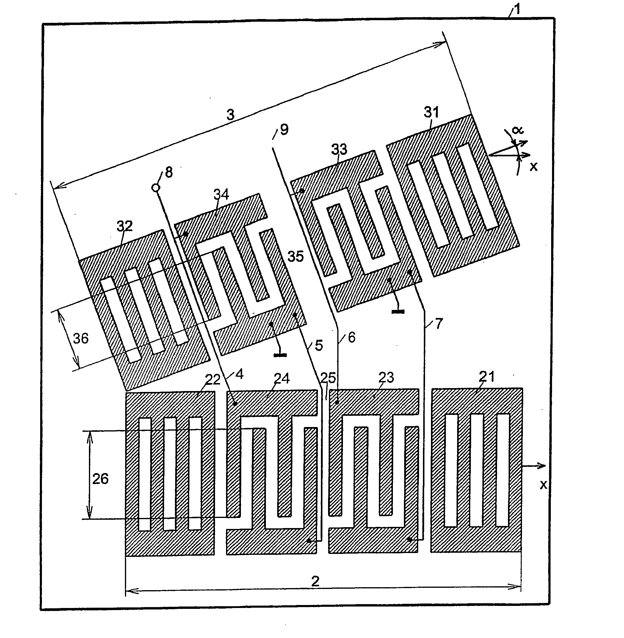
[0044] The oscillator, shown in FIG. 1, consists of a resonator composite as frequency-determining element and a feedback from the output to the input of the composite, which is not shown in the drawing and contains an amplifier. It is assumed that the phase of this feedback is equal to zero. The properties of the resonator composite are described in the following.

[0045] Two two-gate surface wave resonators 2; 3, assembled from reflectors 21; 22 and interdigital converters 23; 24 or from reflectors 31; 32 and interdigital converters 33; 34, are disposed on a substrate 1, which is an ST section of quartz. The two-gate surface wave resonators 2; 3 form a resonator composite. The spreading direction of the two-gate resonator 2, that is, the direction perpendicular to the teeth of the converter 23; 24 and to the strips of the reflectors 21; 22, is aligned parallel to the crystallographic x axis of quartz. For this reason, the temperature dependence of the synchronous frequency of the t...

example 2

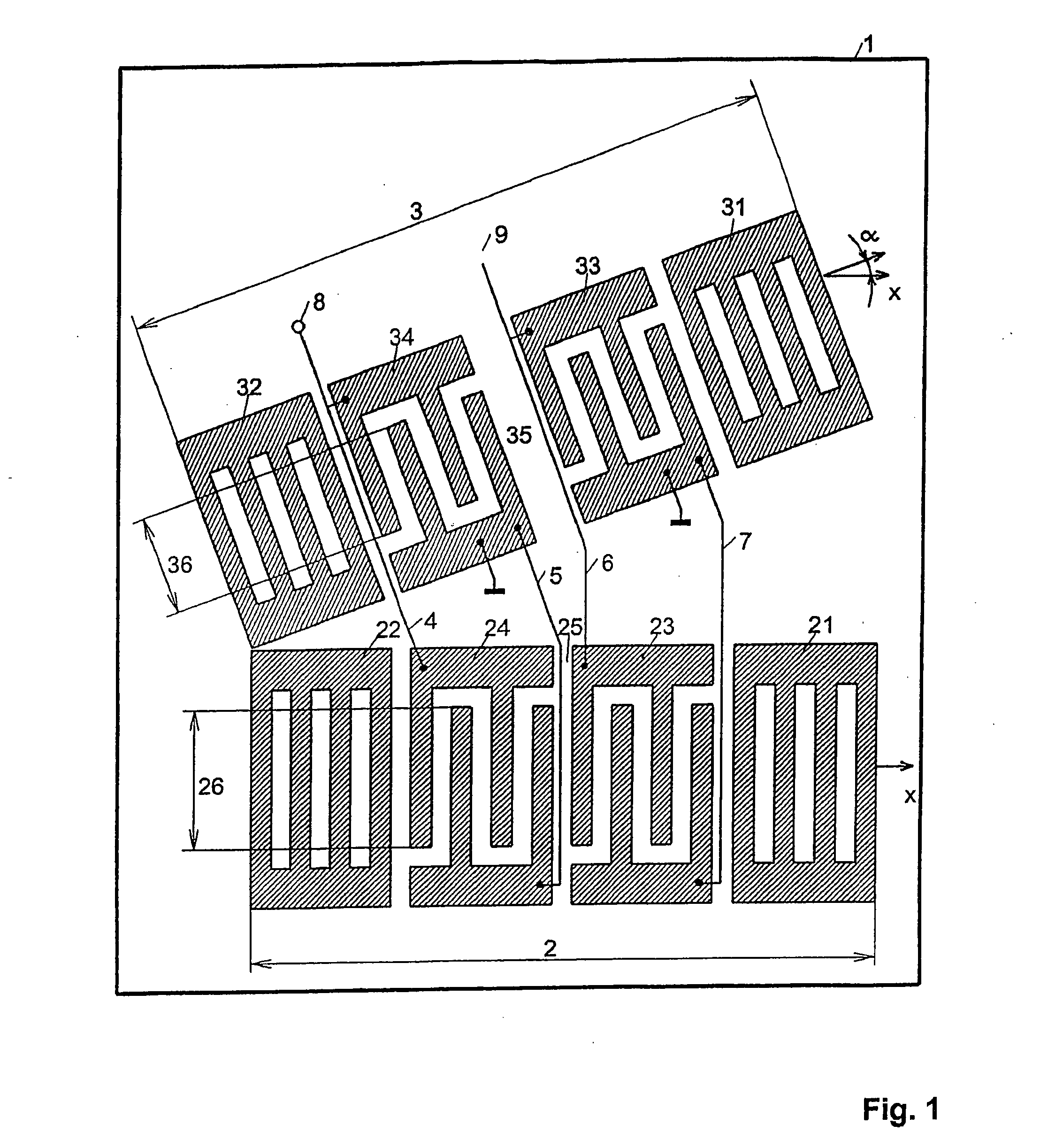
[0048] This example relates to the oscillator shown in FIG. 2. This oscillator consists of a resonator composite as frequency determining element and a feedback from the output to the input of the composite. The feedback contains an amplifier and is not shown. It is assumed that the phase of this feedback is equal to zero. The properties of this resonator composite are described in the following.

[0049] On a substrate 1, which is an ST section of quartz, the surface wave resonators 2; 3, assembled from the reflectors 21; 22 and the interdigital converter 24 and from the reflectors 31; 32 and the interdigital converter 34, are disposed. In addition, a coupling converter 23 or 33 is disposed in the surface wave resonator 2 or 3 between the converter 24 or 34 and the reflector 21 or 31. The surface wave resonators 2; 3 form a resonator composite. The electrodes consist of a layer of aluminum 300 nm thick. The spreading direction of the surface wave resonator 2, that is, the direction p...

example 3

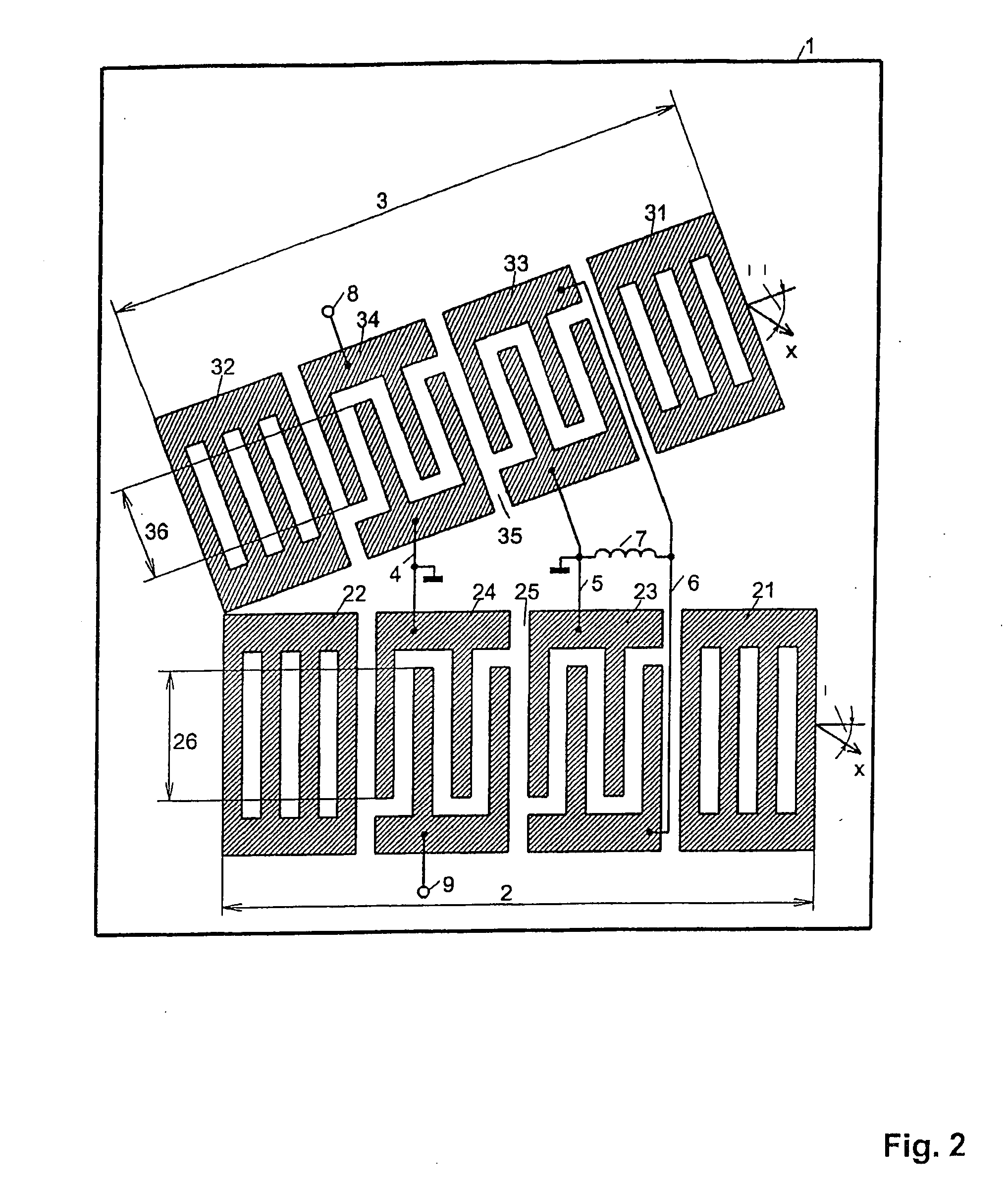
[0051] This example relates to the oscillator with two separate substrates, which is shown in FIG. 3. A surface wave resonator 2, assembled from the reflectors 21; 22 and the interdigital converter 24, is disposed here on a first substrate 10. In addition, a coupling converter 23 is disposed in the surface wave resonator 2 between the converter 24 and the reflector 21. A surface wave resonator 3, assembled from the reflectors 31; 32 and the interdigital converter 34, is disposed on a second substrate 1. In addition, a coupling converter 33 is disposed in the surface wave resonator 3 between the converter 34 and the reflector 31. The surface wave resonators 2; 3 form a resonator composite. The substrate 1 as well as the substrate 10 is an ST section of quartz. In this case, the spreading direction of the surface wave resonator 2, that is, the direction perpendicular to the teeth of the coupling converter 23 and of the converter 24 and to the strips of the reflectors 21; 22, is inclin...


PUM


Abstract

An oscillator or a sensor comprising a unit including two frequency determining elements each of which comprises at least one interdigital converter for acoustic surface waves and a back-coupling circuit comprising an amplifier, wherein the frequency determining elements are distinguished by a temperature dependence of a synchronous frequency. The frequency determining elements are embodied in the form of acoustic surface wave resonators, and the temperature coefficients of n-th order of the synchronous frequency of the two acoustic surface wave resonators have different sings if they are not equal to zero and the temperature coefficients of (n+1st) order of the synchronous frequency of the two acoustic surface wave resonators have the same sign and the temperature coefficients from the first order to (n−1st) order of the synchronous frequency of the two acoustic surface wave resonators are equal to zero if n is greater than 1, wherein n being equal to or greater than 1, c) the ratio between the converter openings and the ratio between the lengths in the direction perpendicular to the edge teeth of the converter and to strips of the object reflectors having different frequency determining elements which are assembled in one unit are selected in such a way that the oscillator frequency variation is minimum within the range of given temperatures.

Description

BACKGROUND OF THE INVENTION [0001] The invention relates to the field of electrical engineering and electronics. Objects, for which the application is possible and appropriate, are components based on acoustic surface waves, such as oscillators and sensors, especially those sensors, for which the variation in the temperature of the oscillator frequency can be adjusted. [0002] Oscillators are known, which comprise a composite of two frequency-determining elements, of which each element contains at least one interdigital converter for acoustic surface waves and a feedback from the output to the input of the composite containing an amplifier, the frequency-determining elements differing from one another due to the temperature dependence of the synchronous frequency. [0003] In the case of a special embodiment, the composite of two frequency-determining elements contains two delay leads, the substrates of which belong to one and the same crystalline section, but use different splitting d...

Claims


Application Information

Patent Timeline
Patent Type & Authority Applications(United States)
IPC IPC(8): H03H9/64H03H9/02
CPCH03B5/326H03H9/02834H03H9/6433H03H9/6469
Inventor MARTIN, GUENTERWEIHNACHT, MANFRED
Owner TELE FILTER
Why Eureka
Try Eureka