Real-time rendering of embedded transparent geometry in volumes on commodity graphics processing units

a graphics processing unit and volume technology, applied in the field of image rendering, can solve the problems of limiting the widespread application of direct volume rendering in particular to applications requiring real-time rendering, and affecting the smoothness of blending

Inactive Publication Date: 2006-09-14
IBM CORP
View PDF16 Cites 29 Cited by
  • Summary
  • Abstract
  • Description
  • Claims
  • Application Information

AI Technical Summary

Benefits of technology

[0012] For a composite image containing a first object and a second object, at least three distinct rendered images are created. A first composite image component is created that contains the volume rendered image. A second composite image component is created containing the volume rendered image and at least one of the first and second geometric representations, and the third composite image component is created containing the volume rendered image and at least one of the first and second geometric representations. Each one of the plurality of composite i

Problems solved by technology

The time and processor requirements associated with these integration computations are significant.
The significant amount of processing time associated with creating 2D projections using direct volume rendering causes a decrease in frame rates in rendering applications, limiting the widespread application of direct volume rendering in particular to applications requiring real-time rendering.
Both of these methods, however, are slow and have significant storage requirements.
This method, however, produces images having a decreased quality as rendering quality is traded-off against relative storage resources.
However, application of the sy

Method used


Image

  • Real-time rendering of embedded transparent geometry in volumes on commodity graphics processing units
  • Real-time rendering of embedded transparent geometry in volumes on commodity graphics processing units
  • Real-time rendering of embedded transparent geometry in volumes on commodity graphics processing units

Examples


Embodiment Construction

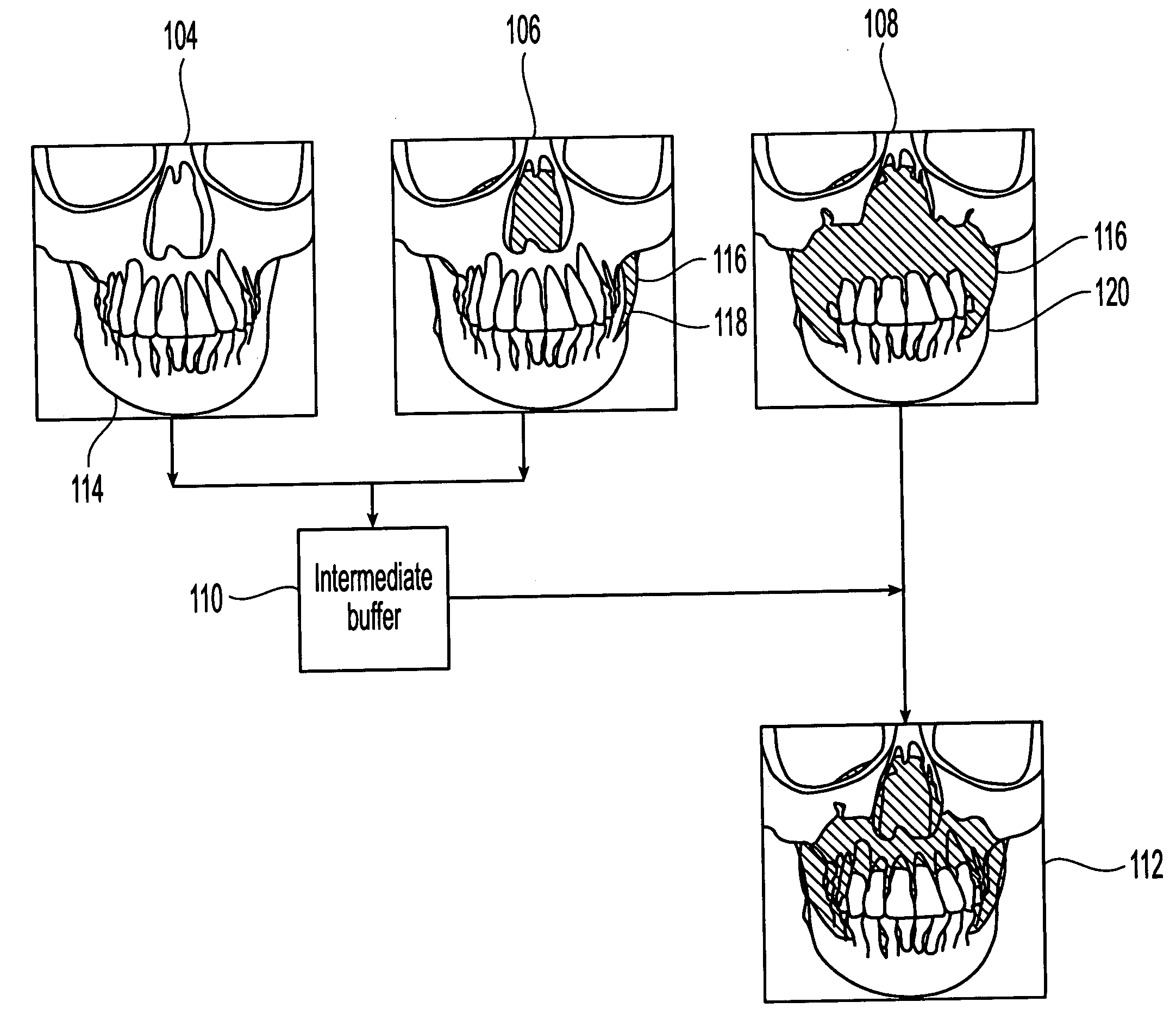
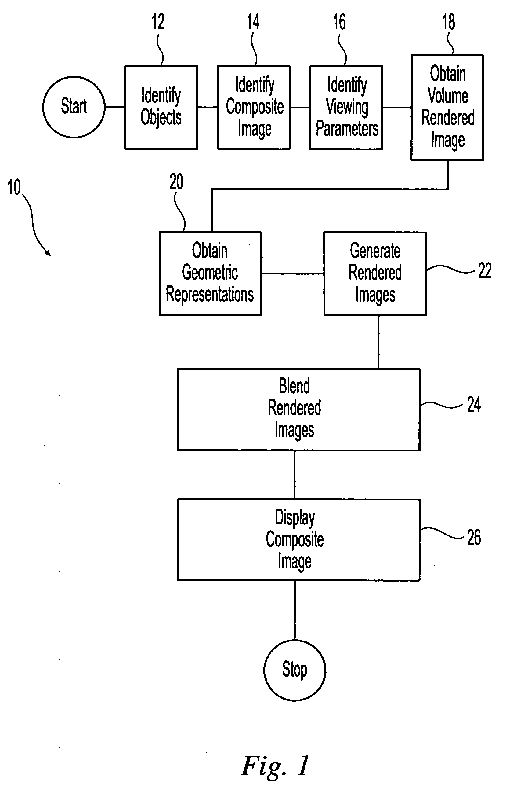
[0020] Referring initially to FIG. 1, the present invention is directed to methods for rendering or creating composite images of two or more objects 10. Initially, the desired composite image is identified by a user. In one embodiment, the user identifies the objects that are to be contained in the composite image 12. Each identified object can be any multidimensional, for example three-dimensional (3D), object or representation. Examples of suitable objects include, but are not limited to, geological formations, meteorological conditions or formations, astronomical formations, physical objects, sports equipment, computer equipment, animals, humans, medical devices and equipment, tactical formations and combinations thereof. The identified objects can possess either an inherent or a user-desired interrelation. Examples of these interrelations include the relationship between a section of human anatomy and a surgical instrument, the geomorphology of an area of the Earth and a mine sh...


PUM


Abstract

A method for creating composite images of multiple objects using standard commodity graphics cards is provided that eliminates the need for expensive specialty graphics hardware for generating real-time renderings of the composite images. After the desired composite image and the objects contained in the composite image are identified, a volume rendered image of a first object is obtained. In addition, at least a first geometric representation and a second geometric representation of a second object based upon a desired composite image of the first and second objects are generated. These geometric representations are preferably polygonal representations. The volume rendered image and the geometric representations are used to create a plurality of composite image components. Each composite image component contains at least one of the volume rendered image, the first geometric representation and the second geometric representation. The composite image components are blended to create the desired composite image.

Description

FIELD OF THE INVENTION [0001] The present invention is directed to image rendering. BACKGROUND OF THE INVENTION [0002] Direct volume rendering is a visualization technique for three-dimensional (3D) objects that represent various types of data including sampled medical data, oil and gas exploration data and computed finite element models. In the petroleum industry, for example, geophysical data are typically acquired as a volumetric dataset, e.g. an ultrasound volume, and visualization techniques, such as direct volume rendering techniques, are used in order to see multiple components of the dataset simultaneously. In addition, geometric objects, such as oil wells or isosurfaces, i.e. polygonal meshes, that denote important geophysical surfaces, need to be inserted into the same scene containing the volume representation of the geophysical data to highlight relevant features in the volume without completely occluding the volume. Similar rendering needs are found in the medical indus...

Claims


Application Information

Patent Timeline
IPC IPC(8): G09G5/00
CPCG09G3/003G09G5/397
Inventor KIRCHNER, PETER DANIELMORRIS, CHRISTOPHER JOEL
Owner IBM CORP
Why Eureka
Try Eureka