Incident assembly of light guide plate

a technology of incident assembly and light guide plate, which is applied in the direction of planar/plate-like light guide, lighting and heating apparatus, instruments, etc., can solve the problems of increasing the thickness of the backlight module, not only the design has very little effect, etc., and achieves the effect of improving the light diffusion effect of an incident light sour

a technology of incident assembly and light guide plate, which is applied in the direction of planar/plate-like light guide, lighting and heating apparatus, instruments, etc., can solve the problems of increasing the thickness of the backlight module, not only the design has very little effect, etc., and achieves the effect of improving the light diffusion effect of an incident light sour

US20060203511A1Inactive Publication Date: 2006-09-14K-BRIDGE ELECTRONICS CO LTD

Image

  • Incident assembly of light guide plate
  • Incident assembly of light guide plate
  • Incident assembly of light guide plate

Examples


Embodiment Construction

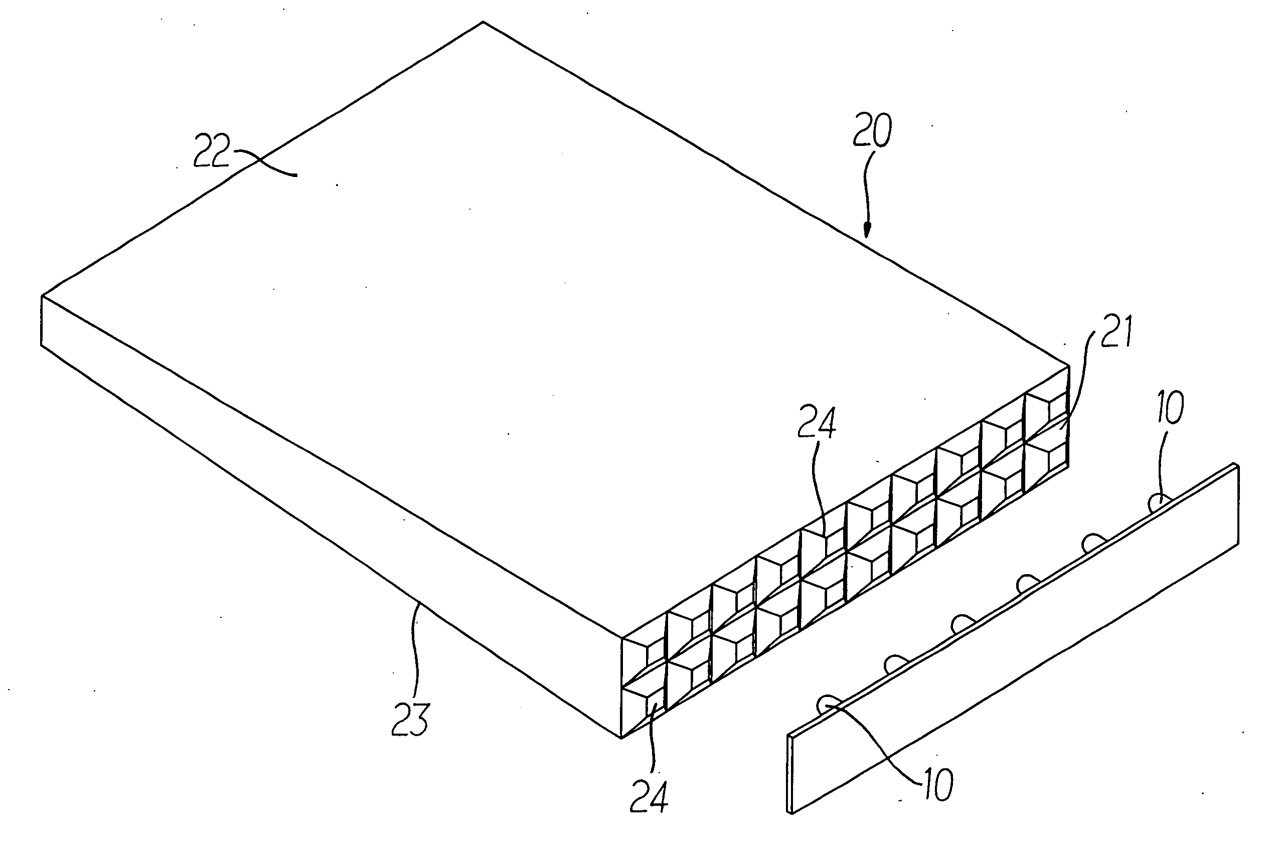
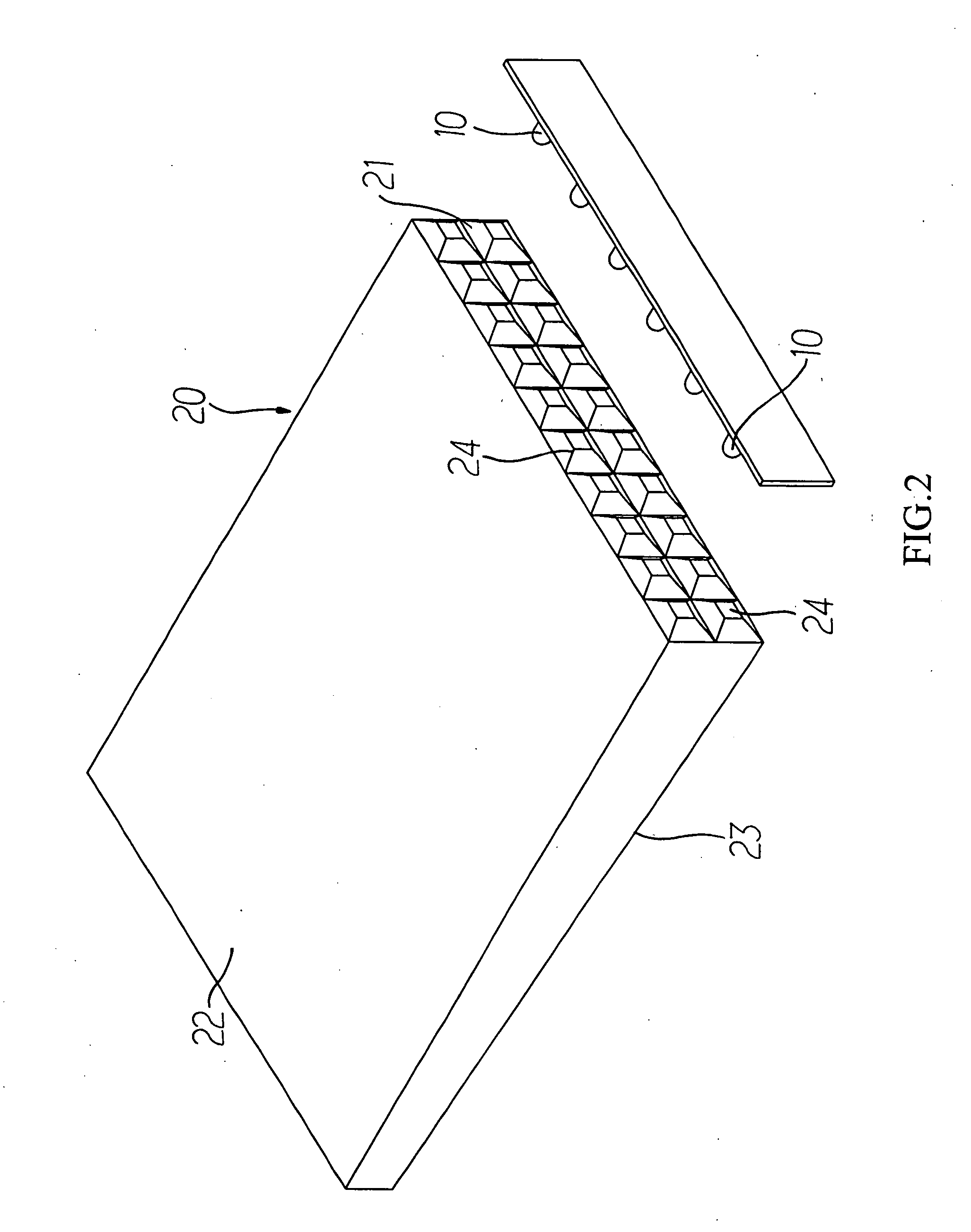
[0013] Referring to FIG. 2, an improved incident assembly of light guide plate in accordance with the present invention is illustrated. The invention comprises a plurality of polyhedral structures disposed on an incident plane of a light guide plate, and the polyhedral structures produce a diffusion effect on a light source of a light emitting device, such that the light source of each light emitting device can be emitted evenly to provide a better display effect for a liquid crystal display.

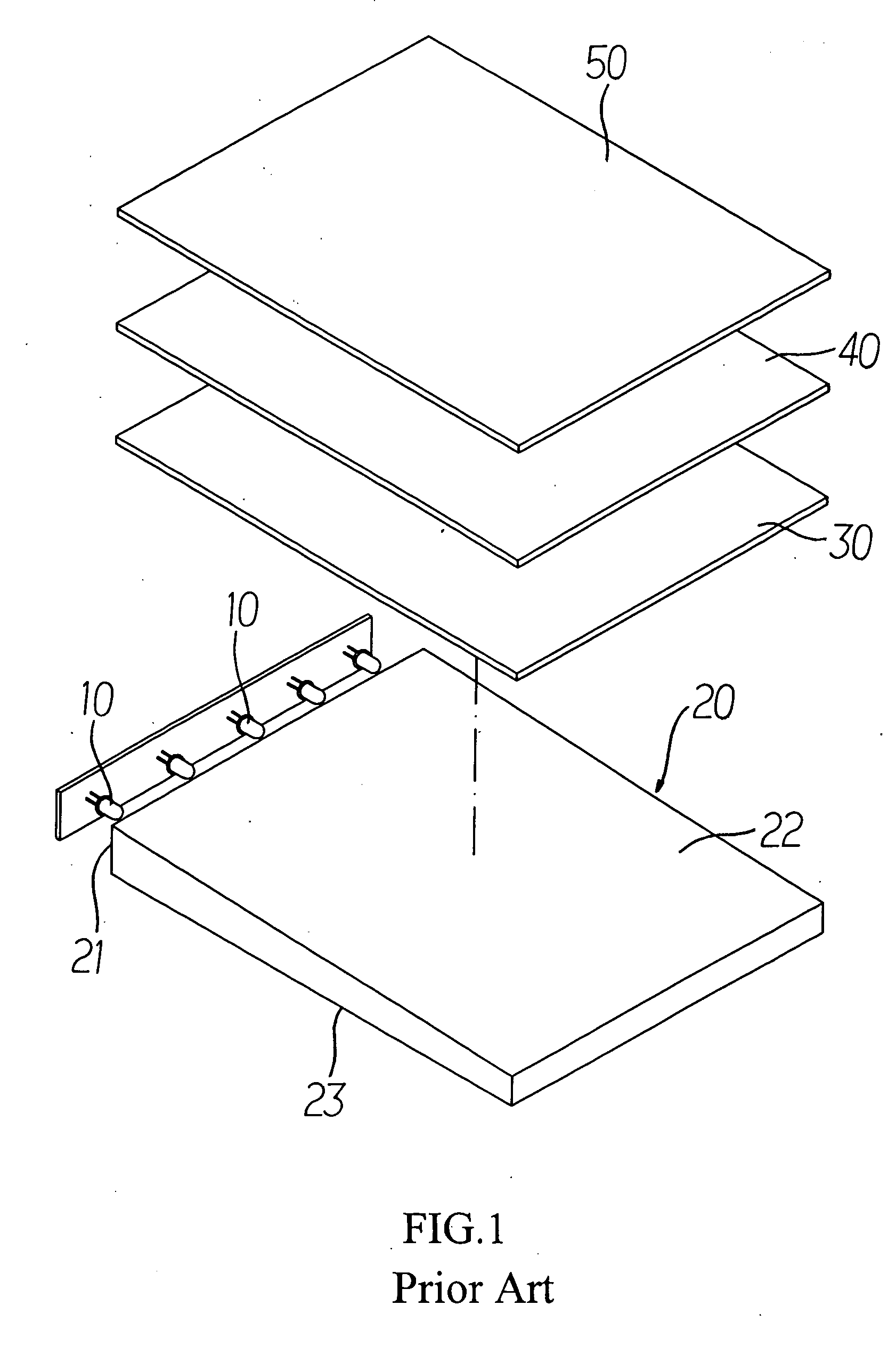
[0014] In actual practices, a backlight module has the same structure as shown in FIG. 1, and the light emitting device (which is a light emitting diode (LED) 10 in this example as illustrated in FIG. 1), a light guide plate 20, a diffuser 30, a prism 40, and a liquid crystal display (LCD) panel 50; wherein the diffuser 30 and the prism 40 are arranged in order and above the light guide plate 20, and the light guide plate 20 is made of a polyester material. The light guide plate 20 comprises an...


PUM

PropertyMeasurementUnit
structuresaaaaaaaaaa
angleaaaaaaaaaa
thicknessaaaaaaaaaa

Abstract

A light guide plate includes an incident plane for receiving a light source of a light emitting device, a bottom surface connected to the incident plane, and an emergent plane corresponding to the bottom surface for outputting the light source of the light emitting device, and the light emitting device is installed on one side of the incident plane of the light guide plate; wherein the incident plane of the light guide plate has a structure consisted of a plurality of polyhedrons, such that an incident light of the light emitting device passes through the polyhedron structure to improve the light diffusion effect and make the light produced by the light emitting device evenly diffused towards the emergent plane of the light guide plate.

Description

BACKGROUND OF THE INVENTION [0001] 1. Field of the Invention [0002] The present invention relates to an improved incident assembly of a light guide plate that can effectively improve the diffusion at an incident plane. [0003] 2. Description of the Related Art [0004] Referring to FIG. 1, the schematic view of a basic architecture and a conventional light source projecting assembly of a general liquid crystal module are shown. The liquid crystal module usually comes with a light emitting device (which is a light emitting diode (LED) 10 in this example as illustrated in FIG. 1), a light guide plate 20, a diffuser 30, a prism 40, and a liquid crystal display panel 50; wherein the diffuser 30 and the prism 40 are arranged in order and disposed above the light guide plate 20, and the light guide plate 20 is made of a polyester material and substantially wedge-shaped. The light guide plate 20 includes an incident plane 21, an emergent plane 22, and a bottom surface 23 having a predetermine...

Claims


Application Information

Patent Timeline
14 Sep 2006
Publication
US20060203511A1
IPC
G11B7/135
CPC
G02B6/0016; G02B6/0071
Inventors
TSENG, WEN-PAO