Vehicle vicinity monitoring apparatus

a monitoring apparatus and vehicle technology, applied in the field of vehicle vicinity + monitoring apparatus, can solve the problems of large error in the measurement of the position or distance up to the object, two imaging units may have slightly different heights and orientations, and the object search area is liable to be shifted excessively

Active Publication Date: 2006-09-14
ARRIVER SOFTWARE AB
View PDF26 Cites 48 Cited by
  • Summary
  • Abstract
  • Description
  • Claims
  • Application Information

AI Technical Summary

Benefits of technology

[0012] It is an object of the present invention to provide a vehicle vicinity monitoring apparatus which is capable of appropriately performing a process of detecting an object in a desired monitoring area around a vehicle.
[0013] Another object of the present invention is to provide a vehicle vicinity monitoring apparatus which is capable of quickly and accurately performing a pattern matching process for setting suitable clipping areas respectively in first and second images and determining a parallax with respect to an object from the clipping areas.
[0016] The object extracting unit may detect an object in each of image areas set by the image area setting unit. The image areas can be related to each other for alignment. Therefore, in a pattern matching process for removing the image of the object extracted from either one of the image areas and moving the removed image in the other image area, the period of time required to achieve a pattern match is reduced almost without any possibility for the image to match another object. Therefore, the pattern matching process can quickly and reliably be performed.
[0018] Since the first image area and the second image area are set based on the actually extracted object, the first image area and the second image area can be related to each other for alignment. Therefore, in a pattern matching process for removing the image of the object extracted from either one of the first and second image areas and moving the removed image in the other image area, the period of time required to achieve a pattern match is reduced almost without any possibility for the image to match another object. Therefore, the pattern matching process can quickly and reliably be performed.
[0020] The first imaging unit may obtain a first target as the first image of the object and the second imaging unit may obtain a second target as the second image of the object at the same height as the first target, and the image area setting unit may set the first image area and the second image area based on the difference between coordinates, in the direction perpendicular to the hypothetical plane, of the first target as the first image and the second target as the second image. Because the difference in the direction perpendicular to the hypothetical plane between the images of the first and second targets that are positioned at the same height is used, the first image area and the second image area can be set quickly and simply. The first target and the second target may be the same target.

Problems solved by technology

Particularly, if the object exists in a distant position, then any slight difference between the mounted angles of the imaging units tends to cause a large error in the measurement of the position of or the distance up to the object.
Actually, however, the two imaging units may have slightly different heights and orientations due to a small distortion of the vehicle itself and manufacturing errors of supports of the imaging units.
In the known position detecting apparatus, as corrective quantities relative to a pitch angle and a pan angle with respect to the initially set optical axis of the imaging unit mounted on the vehicle increase, an image area to be processed which is set depending on an image area determined by the initially set optical axis and an object search area is liable to be shifted excessively, making it difficult to appropriately perform a process of detecting the object in a desired monitoring area around the vehicle.

Method used


Image

  • Vehicle vicinity monitoring apparatus
  • Vehicle vicinity monitoring apparatus
  • Vehicle vicinity monitoring apparatus

Examples


Embodiment Construction

[0054] A vehicle vicinity monitoring apparatus according to an embodiment of the present invention will be described below with reference to FIGS. 1 through 29.

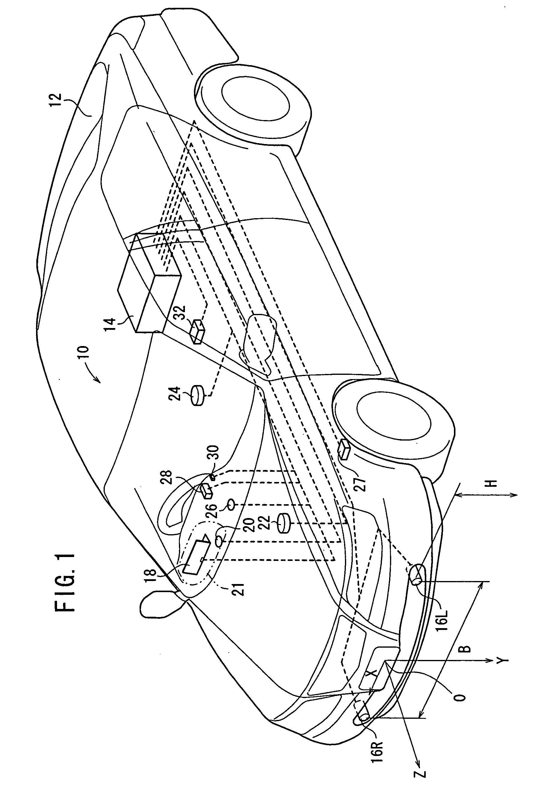
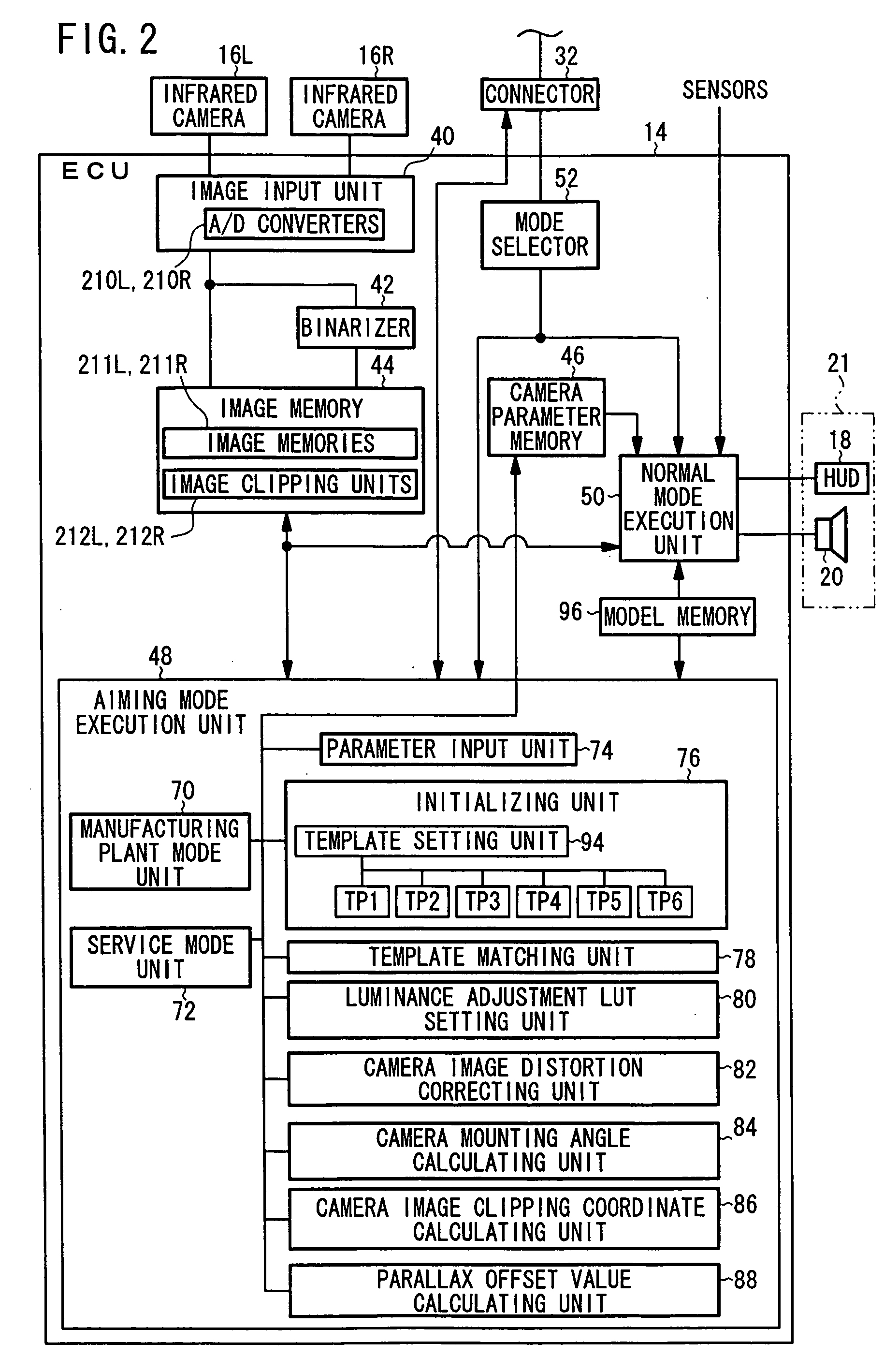
[0055] As shown in FIG. 1, a night vision system (vehicle vicinity monitoring apparatus) 10 according to an embodiment of the present invention is installed on a vehicle 12. The night vision system 10 has an ECU (Electronic Control Unit) 14 serving as a main controller, a left infrared camera 16L (a first imaging unit, hereinafter also referred to as slave camera 16L), a right infrared camera 16R (a second imaging unit, hereinafter also referred to as master camera 16R), an HUD (Head-Up Display) 18 for displaying a detected image, a speaker 20 for outputting an alarm sound, a speed sensor 22 for detecting a running speed, a yaw rate sensor 24 for detecting a yaw rate of the vehicle 12 when the vehicle 12 is driven, a solar radiation sensor 26, a brake sensor 27 for detecting whether the driver of the vehicle 12 has braked th...


PUM


Abstract

A right infrared camera produces a right gray-scale image by imaging aiming targets disposed in a right position, and a left infrared camera produces a left gray-scale image by imaging aiming targets disposed in a left position. An average value of coordinates of the aiming targets in a preset clipping area is determined, and an average value of coordinates of the aiming targets in a preset clipping area is determined. A difference between the average value and the average value is determined, and the clipping area is moved depending on the difference.

Description

BACKGROUND OF THE INVENTION [0001] 1. Field of the Invention [0002] The present invention relates to a vehicle vicinity+monitoring apparatus for extracting an object from an image obtained by an imaging unit that is capable of obtaining images in a visible light range or an infrared radiation range. [0003] 2. Description of the Related Art [0004] There has been developed a vehicle vicinity monitoring apparatus for obtaining images of one object with two imaging units mounted on a vehicle, for example, either measuring the distance up to the object based on the parallax between the obtained images, or measuring the position in an actual space of the object with respect to the vehicle, and informing the driver of whether there is an obstacle ahead of the vehicle or not (see Japanese Laid-Open Patent Publication No. 2003-216937). [0005] According to the developed vehicle vicinity monitoring apparatus, after the object is detected in the two images obtained by the imaging units, the par...

Claims


Application Information

Patent Timeline
Patent Type & Authority Applications(United States)
IPC IPC(8): G05D1/00G06K9/00H04N7/18
CPCB60W2420/40B60W2540/12G06K9/00805G06V20/58
Inventor WATANABE, MASAHITOSAKA, MASAKAZUNAGAOKA, NOBUHARU
Owner ARRIVER SOFTWARE AB
Why Eureka
Try Eureka