
Pattern recognition apparatus and method

a technology of pattern recognition and apparatus, applied in image analysis, instruments, computing, etc., can solve the problems of long time and a large amount of memory for registration, insatisfactory, and object in a specific direction cannot be detected by restrictions, so as to improve the efficiency of memory capacity, speed up the retrieval, and improve the effect of memory capacity

Inactive Publication Date: 2006-09-14
KK TOSHIBA
View PDF3 Cites 65 Cited by
  • Summary
  • Abstract
  • Description
  • Claims
  • Application Information

AI Technical Summary

Benefits of technology

The present invention is a pattern recognition apparatus that can compare an image with a previously registered model to recognize an object. It includes an image input unit, a feature point extraction unit, a triangulation unit, a feature point selection unit, a basis calculation unit, a partial pattern extraction unit, a table memory unit, an index retrieval unit, and a pattern similarity calculation unit. The invention improves the efficiency of memory capacity and speed up the retrieval while keeping the conventional property tolerance against occlusion. It allows for efficient model search and high-speed retrieval.

Problems solved by technology

However, in the above pattern recognition method, the order of the number of combinations of three feature points becomes O(n3), and there is a problem that when the number of feature points is increased, a long time and a large amount of memory for registration are required.
Besides, according to the second approach, there is a problem that an object in a specific direction can not be detected by the restrictions.
Further, in these speedup approaches, it is not essential to reduce the number of combinations at the time of registration and is not satisfactory.

Method used


Image

  • Pattern recognition apparatus and method
  • Pattern recognition apparatus and method
  • Pattern recognition apparatus and method

Examples


first embodiment

[0036] Hereinafter, a pattern recognition apparatus of a first embodiment of the invention will be described with reference to the drawings.

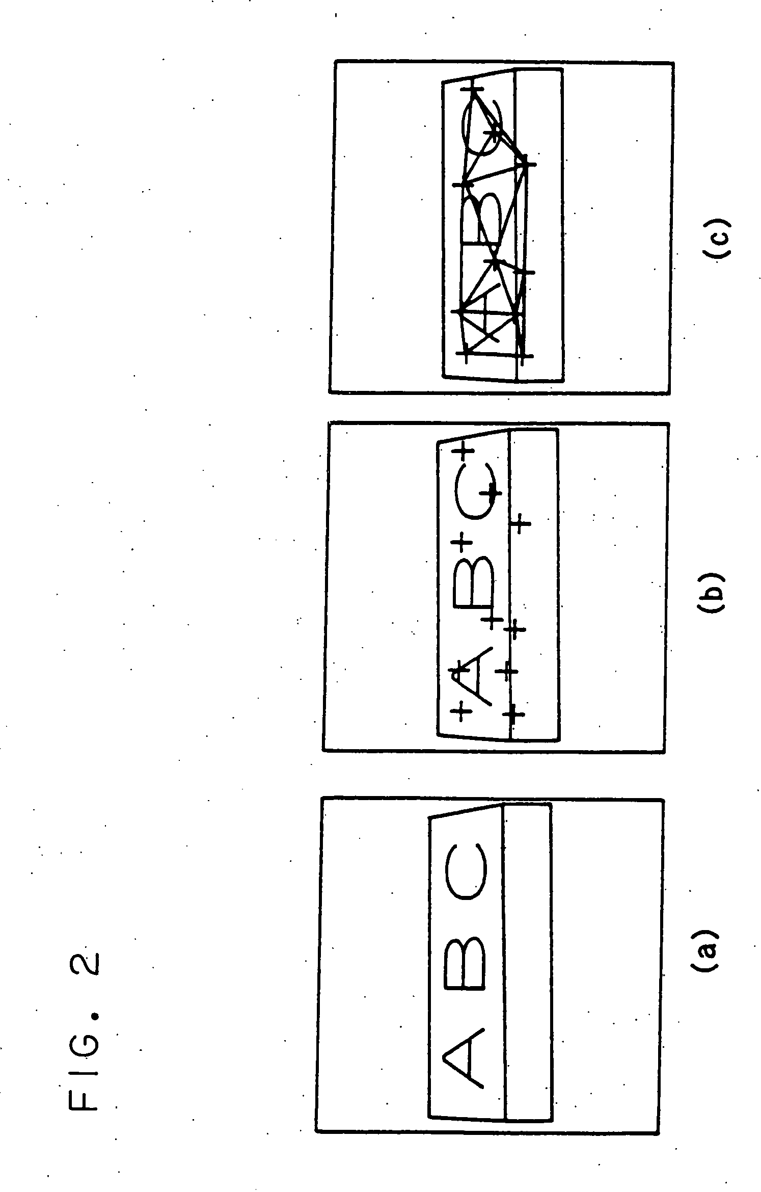
[0037] This embodiment relates to a method of detecting the position and pose of an object from an image. Although any target object be adopted as an object to be recognized, in this embodiment, an example in which a box object as shown in FIGS. 2A to 2C is detected is used for the description.

[0038] In this embodiment, an image in which an arbitrary position and an arbitrary pose of the box are photographed is made one model, and images relating to boxes of various positions and poses are registered as plural models.

[0039] With respect to a detection object image in which the same box is photographed, it is judged that the image is similar to which model, and the position and pose of the box photographed in the detection object image are recognized.

[0040] Then, the following description is divided into two phases of; “registration of model”...

second embodiment

[0152] A second embodiment will be described.

[0153] Although the number of combinations can be reduced by using the Delaunay triangulation, it is difficult to detect plural objects that differ in size from each other, in view of the property of the Delaunay the Delaunay triangulation; only vicinity triangles are generated from the property of the Delaunay triangulation. In order to further improve the accuracy, consideration is given to a case where various scale triangles are generated. Here, plural feature point sets are formed, and by changing the way of forming them, various scale triangulations are generated.

(1) First Method

[0154] A description will be given to a first method of generating various scale triangulations.

[0155] First, the feature point detection is made by the feature point extraction part 2 to generate a feature point set. At each of the feature points, there is something like an evaluation value by the feature point extraction part 2. For example, in the ca...

third embodiment

[0164] Although the recognition results of the first and the second embodiments relate to only the position and pose of the object, a method of obtaining a place of a saliency point of a recognized object will be described. A saliency point estimation part having the following function is added to the object recognition part 11.

[0165] For example, when a description is made by use of FIG. 5-501, the saliency point is the corner part of a box and is a point indicated by a white circle mark.

(1) Operation of Saliency Point Estimation Part

[0166] The operation of the saliency point estimation part will be described.

(1-1) Registration of Saliency Point of Model

[0167] First, a saliency point of a model is registered. The saliency point of the model is registered in FeaPnt as the point different from the feature point at the time of registration of the model. For example, in the example of FIG. 5-501, in the case where the box is registered as the model, the point of the corner of th...


PUM


Abstract

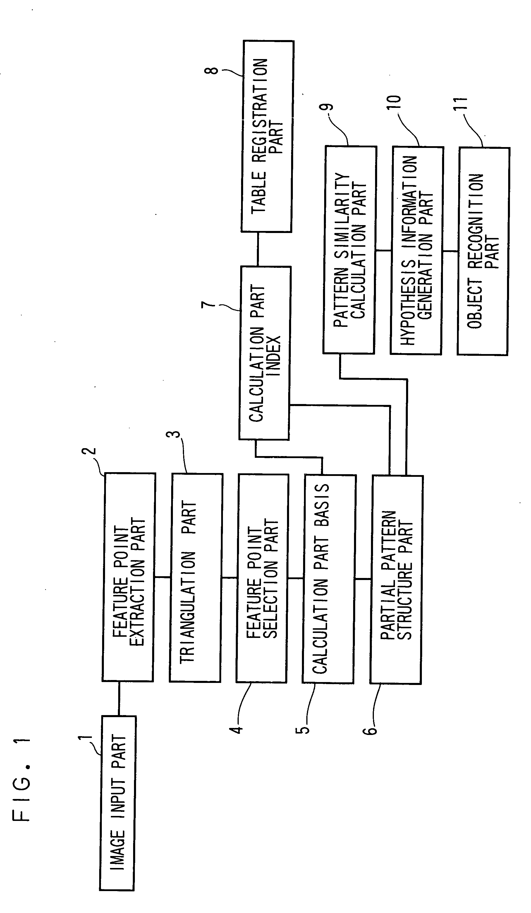
A pattern recognition apparatus compares an image including a photographed object to be recognized with a model previously registered in a table and recognizes the object to be recognized, and the pattern recognition apparatus includes an image input part 1, a feature point extraction part 2, a triangulation part 3, a feature point selection part 4, a basis calculation part 5, a partial pattern structure part 6, an index calculation part 7, a table registration part 8, a pattern similarity calculation part 9, a hypothesis information generation part 10, and an object recognition part 11. Plural feature points are extracted from the image of the object to be recognized, triangulation of a feature point set is obtained, and a combination of plural feature points is selected from plural feature points in accordance with the extracted triangulation.

Description

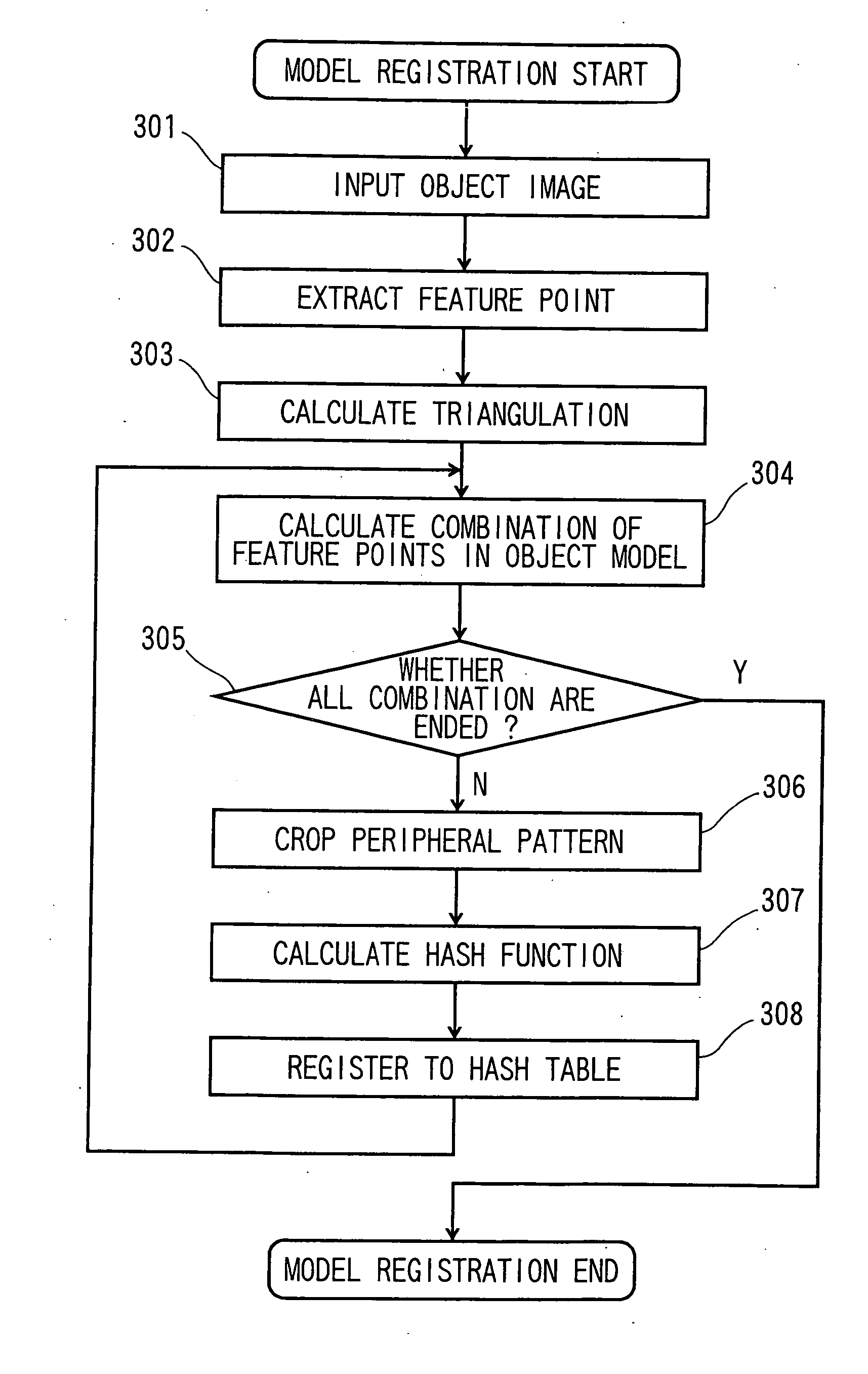
CROSS-REFERENCE TO RELATED APPLICATIONS [0001] This application is based upon and claims the benefit of priority from the prior Japanese Patent Application No. 2005-67500, filed on Mar. 10, 2005; the entire contents of which are incorporated herein by reference. TECHNICAL FIELD [0002] The present invention relates to a pattern recognition apparatus and method. BACKGROUND OF THE INVENTION [0003] A technique to detect and recognize the position, pose and shape of a specific object from an image is an important technique in computer vision. Japanese Patent Application Publication(KOKAI) No. JP-A-2003-242509 discloses a conventional pattern recognition method to recognize a registered object from an image. [0004] This method has following properties in order to deal with partial occlusion. [0005] The first property is to make the registration of partial information and the multiple description of a model. [0006] The second property is to make the description of the model based on an inv...

Claims


Application Information

Patent Timeline
Patent Type & Authority Applications(United States)
IPC IPC(8): G06K9/00G06K9/46G06T15/00G06T7/00G06V10/44
CPCG06K9/4604G06K9/6211G06V10/757G06V10/44
Inventor YAMAGUCHI, OSAMU
Owner KK TOSHIBA
Learn More