Cleaning apparatus and image forming apparatus provided therewith

a technology of cleaning apparatus and image forming apparatus, which is applied in the direction of optics, instruments, electrography/magnetography, etc., can solve the problems of accumulating on the surface, affecting the cleaning performance of the surface, and removing the image that disturbs the electrostatic latent image, etc., and achieves the effect of suitable cleaning performan

Inactive Publication Date: 2006-09-14
KYOCERA DOCUMENT SOLUTIONS INC
View PDF4 Cites 25 Cited by
  • Summary
  • Abstract
  • Description
  • Claims
  • Application Information

AI Technical Summary

Benefits of technology

[0021] With this structure, unwanted toner is reliably sent toward the discharging member as speedily as possible without allowing toner removed from the surface of the image carrying body to keep in contact with the surface of the image carrying body and accumulate thereon, or without allowin

Problems solved by technology

With such a transfer method, however, residual toner may result because there is a possibility that a small amount of toner is not transferred to paper and remains on the surface of the photoconductor drum after a toner image is transferred to the paper.
On the other hand, when an amorphous silicon photoconductor is used as the photoconductor, there often occurs image deletion that disturbs an electrostatic latent image by absorption of moisture by electrical discharge products formed on the surface of the photoconductor.
With this structure, however, when the toner that has started moving from the cleaning roller toward the discharging member does not reach the dischar

Method used


Image

  • Cleaning apparatus and image forming apparatus provided therewith
  • Cleaning apparatus and image forming apparatus provided therewith
  • Cleaning apparatus and image forming apparatus provided therewith

Examples


Embodiment Construction

[0031] Hereinafter, embodiments of the present invention will be described with reference to FIGS. 1 to 9.

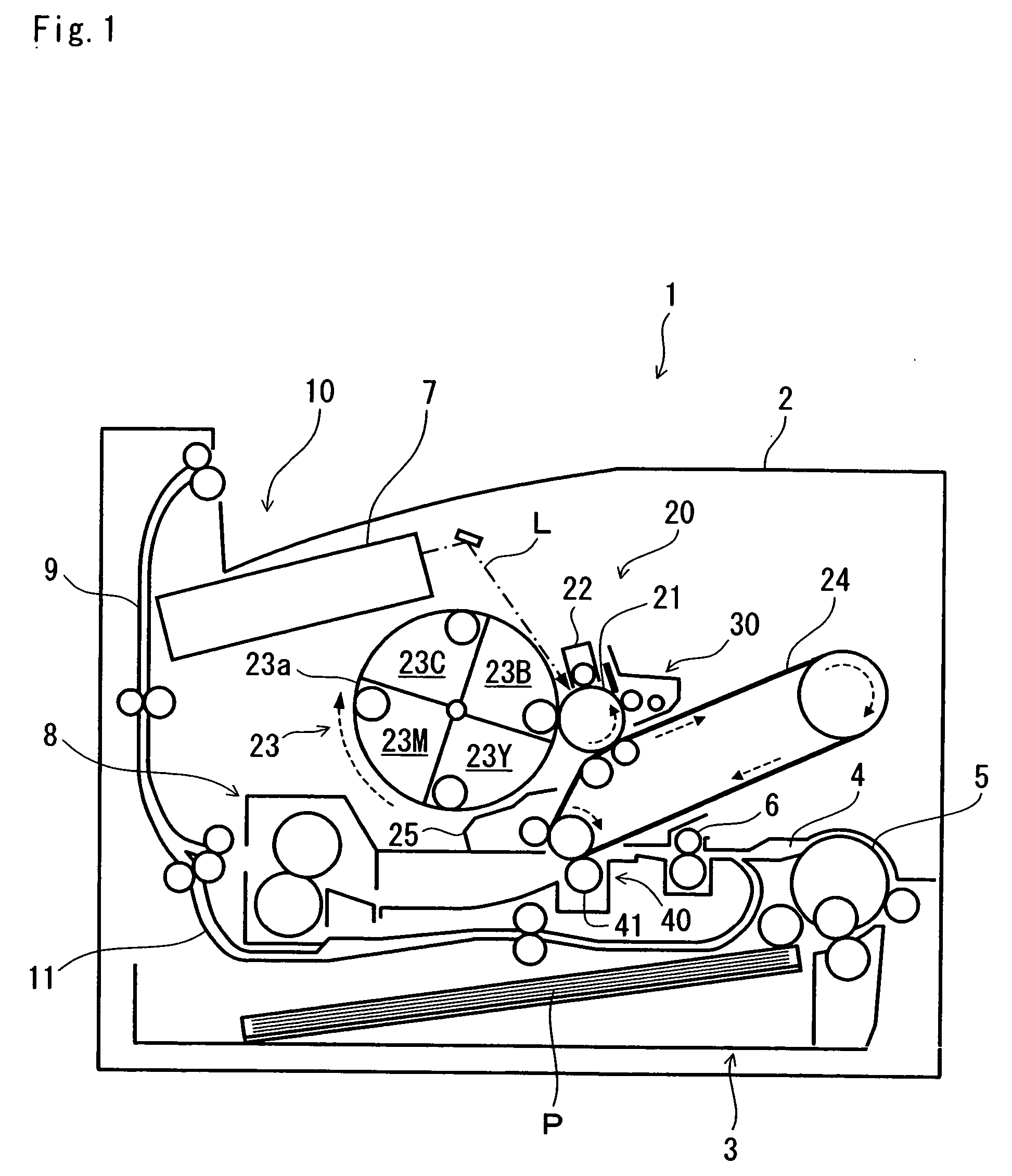
[0032] First, the schematic structure of the image forming apparatus provided with the cleaning apparatus of the embodiments of the present invention will be described with reference to FIG. 1. FIG. 1 is a schematic vertical sectional left side view showing the schematic structure of a color printer, which is an example of the image forming apparatus. This color printer is a type of printer that uses an intermediate transfer belt. In FIG. 1, a front face of the printer faces rightward, and a back face thereof faces leftward.

[0033] As shown in FIG. 1, a paper cassette 3 is located inside a main body 2 of a printer 1 in the lower portion of the main body 2. The paper cassette 3 accommodates a stack of paper P. In FIG. 1, the paper P is sent to the upper right of the paper cassette 3. The paper cassette 3 can be horizontally pulled out from the front face of the main body 2, that...


PUM


Abstract

A cleaning apparatus 30 is provided with a cleaning roller 33 that is a rotating member, a scraper 35, a partition wall 36, opening/closing members 37, and a discharge screw 38 that is a discharging member. The scraper 35 supported by the partition wall 36 scrapes toner by bringing the tip thereof into contact with the cleaning roller 33. The partition wall 36 has a plurality of openings 36a, and partitions between a space S1 formed on an upstream side of the cleaning roller 33 in a rotation direction of a drum and a space S2 in which the discharge screw 38 is provided. The opening/closing members 37 are individually provided for the openings 36a so as to permit toner to move through the openings 36a only in a direction from the space S1 to the space S2. With this structure, it is possible to make toner present in the vicinity of the cleaning roller 33 smoothly move toward the discharge screw 38.

Description

[0001] This application is based on Japanese Patent Application No. 2005-065191 filed on Mar. 9, 2005, the contents of which are hereby incorporated by reference. BACKGROUND OF THE INVENTION [0002] 1. Field of the Invention [0003] The present invention relates to a cleaning apparatus that cleans the surface of an image carrying body by removing toner remaining thereon after transferring a toner image to paper, and to an image forming apparatus provided with the cleaning apparatus. [0004] 2. Description of Related Art [0005] In electrophotographic image forming apparatuses, a widely-used method of transferring a toner image to paper is as follows. A transfer region is formed by making a photoconductor drum, which is an image carrying body, and a transfer roller, which is a transfer member, come into contact with each other, or by bringing them close to each other, and then paper is inserted through the transfer region thus formed, thereby transferring a toner image formed on the surf...

Claims


Application Information

Patent Timeline
IPC IPC(8): G03G21/00
CPCG03G21/10
Inventor HONDA, MITSUNOBUISHINO, MASAHITO
Owner KYOCERA DOCUMENT SOLUTIONS INC
Why Eureka
Try Eureka