
Wireless repeater with feedback suppression features

a wireless repeater and feature technology, applied in the field of wireless repeaters, can solve the problems of repeater not allowing the channel profile itself to be reconfigured, the same wireless repeater unit cannot be used in different regions, and the battery drains more quickly, so as to improve the server-donor feedback suppression effect of the uni

Inactive Publication Date: 2006-09-14
ANDREW CORP
View PDF68 Cites 129 Cited by
  • Summary
  • Abstract
  • Description
  • Claims
  • Application Information

AI Technical Summary

Benefits of technology

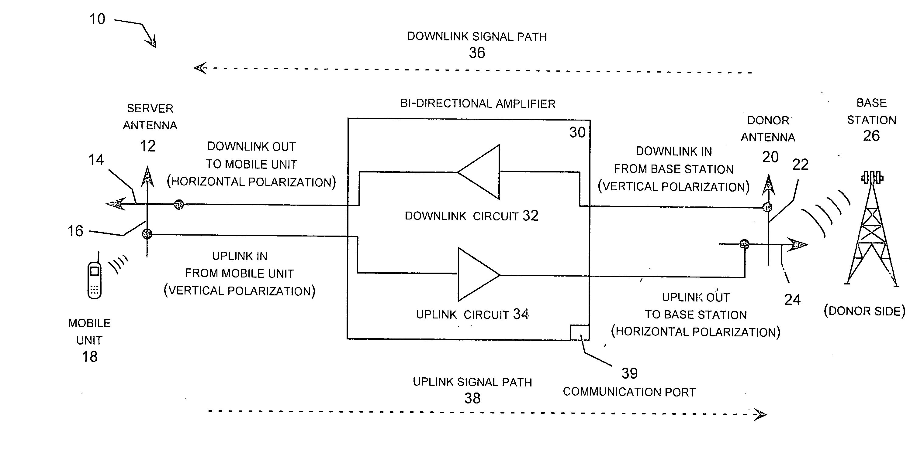
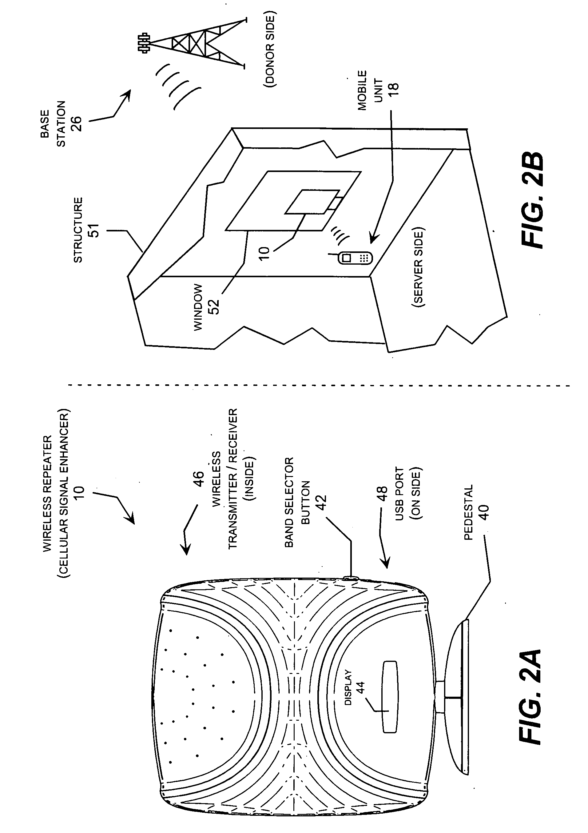
[0009] The present invention meets the needs described above in a wireless repeater with a number of mechanical features designed to improve the server-donor feedback suppression of the unit. These features include a multi-purpose mounting plate for the donor antenna that supports the donor antenna feed circuit board and associated donor antenna elements mounted on one side of the multi-purpose mounting plate, and the duplex repeater electronics board mounted on the other side. The server side has a similar multi-purpose configuration with the server antenna feed circuit board mounted to one side and the duplex repeater electronics board sandwiched between the server and donor mounting plates. In this configuration, the donor and server antennas are supported within an common enclosure and pointed in opposite directions. In other words, to provide a compact and portable wireless repeater unit, the server and donor antennas are housed within a common enclosure in a back-to-back configuration with the server and donor antennas pointing in opposite directions, such that the unit can be placed in a window with the donor antenna pointing out the window and the server antenna pointing into the structure.
[0010] To enhance the server-donor antenna isolation, one or both mounting plates may include corner tabs and / or side tabs, which may be asymmetric, and raised walls around one or both mounting plates. In addition, the radomes covering the donor antenna and / or server antennas may carry one or more parasitic conductors, such as a two parasitic strips arranged in parallel lines or for parasitic strips arranged in a square configuration. To provide electromagnetic isolation in a light weight structure, the multi-purpose mounting plate is preferably manufactured from aluminum.
[0012] The server and / or donor mounting plates may also include one or more walls forming one or more isolation zones that substantially enclose certain portions of the electronic board to reduce the release of electromagnetic energy radiating from these zones of the electronic board. The server and / or donor mounting plates may also include one or more corner tabs for reducing the amount of energy radiated by the donor antenna that propagates around the common housing and into the server antenna. Further, the server and / or donor mounting plate may include one or more corner tabs for reducing the amount of energy radiated by the donor antenna that propagates around the common housing and into the server antenna. Some or all of these features may also be arranged in asymmetrical sets.

Problems solved by technology

In addition, low signal strength causes the wireless telephone to increase its transmission power, which drains the battery more quickly.
While this was the intended result of the spectrum auction process, the resulting variation in the frequency channel profile from region to region presents a challenge for the designers of wireless repeaters intended for installation in the premises of the end-use customers, mainly homes and offices.
Although wireless repeaters have been developed that permit the user to select among a variety of frequency bands within a predefined channel profile, prior wireless repeaters have not permitted the channel profile itself to be reconfigured.
As a result, the same wireless repeater unit cannot be used in different regions that have implemented different channel profiles.
This generally increases the tendency of the repeater to develop positive feedback instability, thereby limiting the gain that can be effectively applied by the unit.

Method used


Image

  • Wireless repeater with feedback suppression features
  • Wireless repeater with feedback suppression features
  • Wireless repeater with feedback suppression features

Examples


Embodiment Construction

[0034] The present invention may be implemented as an improvement to the wireless repeater described in commonly-owned copending U.S. patent application Ser. No. 10 / 375,879 entitled “Cellular Signal Enhancer” filed Feb. 26, 2003. The present invention may be embodied in a wireless repeater suitable for use in a building or other structure, such as a home or business. Several embodiments are shown and described below that each include a number of features to improve the server-donor feedback suppression, which is also referred to as isolation. These features include a multi-purpose mounting plate for the donor antenna that includes the donor antenna feed circuit board and associated donor antenna elements mounted on one side of the multi-purpose mounting plate, and the duplex repeater electronics board mounted on the other side. The server side has a similar configuration, with the donor and server antennas pointed in opposite directions and the duplex repeater electronics board sand...


PUM


Abstract

A wireless repeater with features that improve the server-donor antenna isolation including multi-purpose server and donor mounting plates that each carry an antenna feed circuit board and associated antenna elements mounted in a back-to-back arrangement with the duplex repeater electronics board sandwiched between the server and donor mounting plates. To improve the server-donor antenna isolation, one or both mounting plates may include corner, side tabs, which may be asymmetric, and raised walls around one or both mounting plates. In addition, the radomes covering the donor antenna and / or the server antennas may carry one or more parasitic conductors, such as a two parasitic strips arranged in parallel lines or for parasitic strips arranged in a square configuration.

Description

REFERENCE TO RELATED APPLICATIONS [0001] This application claims priority to commonly-owned copending U.S. Provisional Patent Application Ser. No. 60 / 660,928 entitled “Improved Cellular Signal Enhancer” filed Mar. 11, 2005, which is incorporated herein by reference. This application also incorporates by reference commonly-owned copending U.S. patent application Ser. No. 10 / 375,879 entitled “Cellular Signal Enhancer” filed Feb. 26, 2003, which is also incorporated herein by reference. This application further incorporates by reference commonly-owned copending U.S. patent application Ser. No. 11 / 127,668 entitled “Mounting Pedestal For A Cellular Signal Enhancer” filed May 13, 2005.TECHNICAL FIELD [0002] The present invention is generally related to wireless repeaters, which are also referred to as cellular signal enhancers. More particularly, the invention relates to a wireless repeater with feedback suppression features including mechanical tabs, raised walls, circuit board isolation...

Claims


Application Information

Patent Timeline
IPC IPC(8): H04B7/15
CPCG08C2201/40H04B7/15535H04B7/15542H04B7/1555H04B7/15571H04B7/15578H04B7/15585
Inventor RUNYON, DONALD L.THOMPSON, STEPHEN BRETTMAXWELL, JAMES WILLIAMMCKAY, DAVID L. SR.
Owner ANDREW CORP
Learn More