Devices, Methods and Kits for Radiation Treatment via a Target Body Surface

Inactive Publication Date: 2006-09-14
VALAM CORP
View PDF16 Cites 142 Cited by
  • Summary
  • Abstract
  • Description
  • Claims
  • Application Information

AI Technical Summary

Benefits of technology

[0016] The radiation applicator may include one or more radiation source(s) coupled to a substrate (e.g., a layer, such as a fabric strip on which radiation source(s) are positioned for presentation of radiation to a target body surface). In one embodiment, a controller and a power source are also coupled to a substrate. In another e

Problems solved by technology

In atopic dermatitis, the skin becomes extremely itchy.
Scratching leads to redness, swelling, cracking, “weeping” clear fluid, and finally,

Method used


Image

  • Devices, Methods and Kits for Radiation Treatment via a Target Body Surface
  • Devices, Methods and Kits for Radiation Treatment via a Target Body Surface
  • Devices, Methods and Kits for Radiation Treatment via a Target Body Surface

Examples


example 1

[0109] UV LED (310 nm) chips from S-ET (Columbia, S.C.) were used as one radiation (light in this case) source 102a; the chip was mounted on a gold patterned aluminum nitride sub-mount and further mounted on a Kovar header. The patterning was performed by Advanced Thin Film, Fremont, Calif. The chips were bonded to a eutectic metal layer (e.g. gold-tin alloy) which was deposited on parts of the gold portions of a sub-mount and then to a TO-46 (well-known to those skilled in the art) header package. An aluminum reflector was attached with epoxy to the header which serves to reflect the light toward the spectral conditioner (e.g. a lens in this case). In this example, a patient interface was not included in the assembly. The radiation applicator was then applied to the skin for approximately 14 minutes. At 14 minutes, the dose was sufficient to sunburn a region of one square centimeter (the region had previously been assessed to require 350 mJ / cm2 for an MED at 310 nm). The required v...

example 2

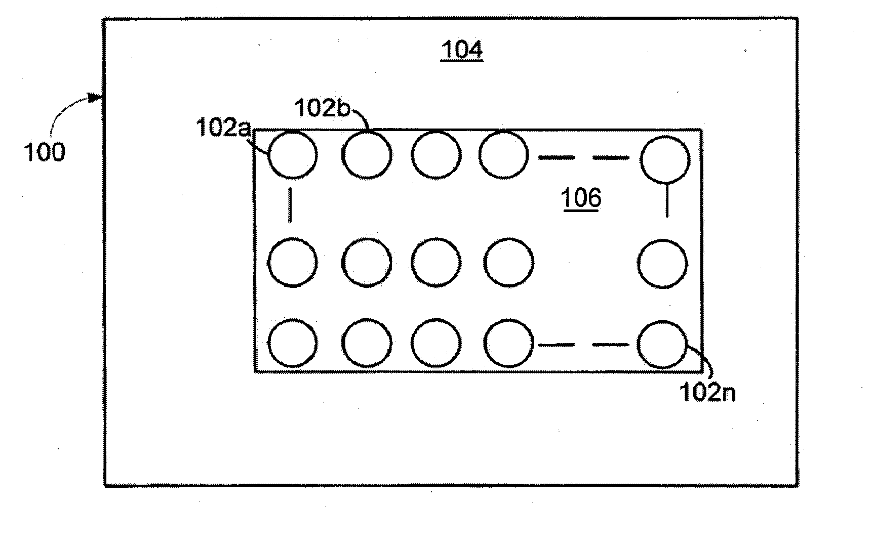
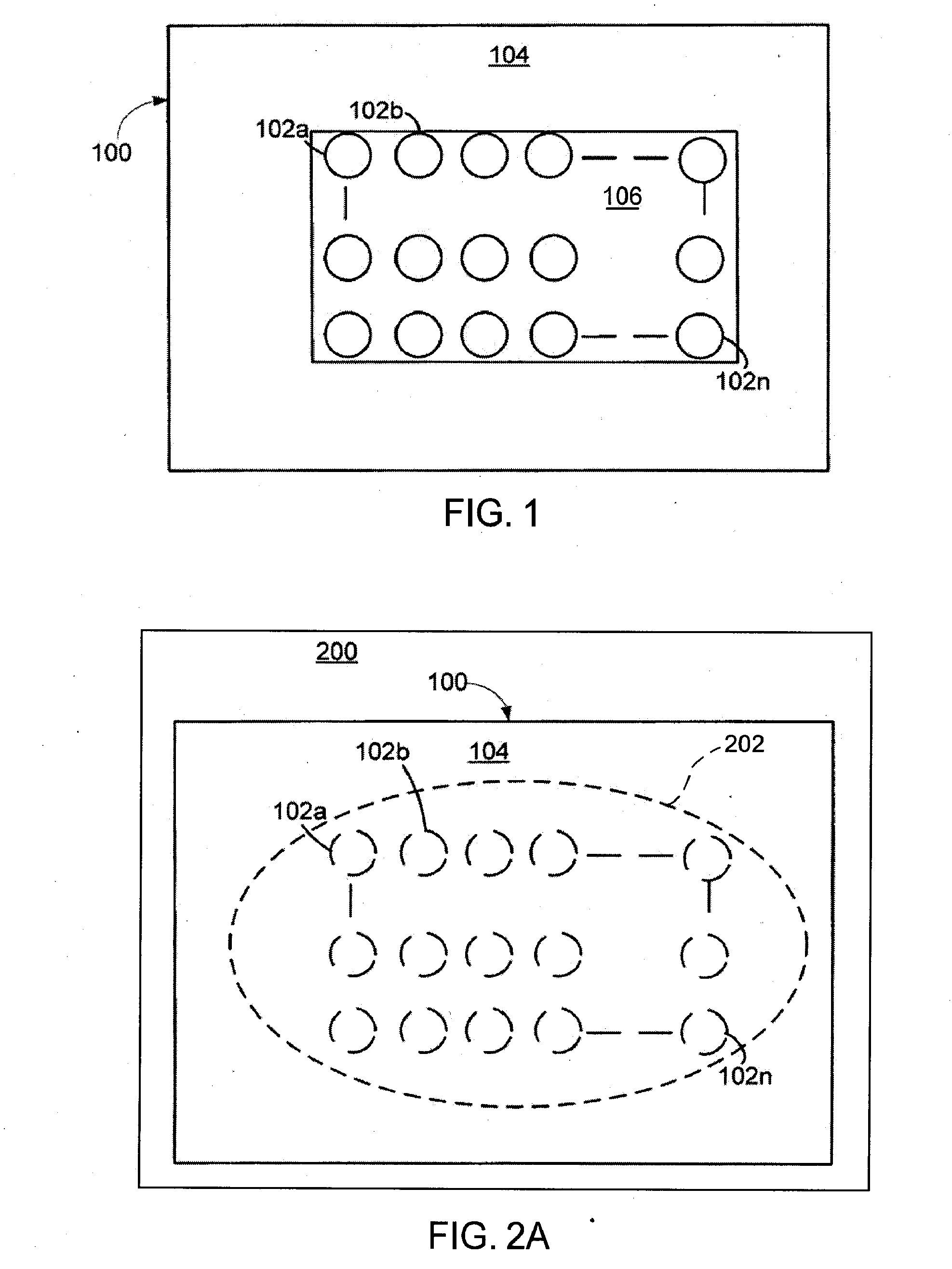
[0110] In another example, a radiation applicator was made using the materials and techniques described with respect to Example 1. However, a UV LED submount containing four LEDs was used for radiation source(s) 102 (e.g. 102a-102n) instead of the UV LED chips. This alternate radiation source 102 resulted in a sunburn over an area of 2 cm2 in approximately 3.5 minutes with a voltage of approximately 6 Volts and using 80 milliamps of current.

[0111] In applying the device of Example 2 to, for example, psoriasis, which has an average size of a diseased area of approximately 100 cm2 (approximately 1% of the body surface area of a patient), is capable of giving a patient a sunburn over a 100 cm2 area by applying a therapeutic dose via the 2 cm2 sized radiation applicators to 50 2 cm2 patches, one patch at a time, each for 3.5 minutes. Radiation applicator 100 is capable of delivering a therapeutic dose of ultraviolet light to these 50 patches, in approximately 50×3.5 minutes=175 minutes...

example 3

[0112] In this example, a covering (e.g. 513 in FIG. 5D) was applied directly over the UV LED 502. The silicone used, RTV615, available from GE Silicones was chosen for its patient compatability and its index of refraction which is well-matched to the surface of the LED 502. With this configuration, when the experiment in example 1 was repeated, a sunburn would be achieved in 8 minutes, indicating that the optical output was 612 micro Watts for this experiment, which is a 1.8 fold increase over experiment 1. The resulting device was more comfortable to wear. This example illustrates the manner in which covering 513 can be used to enhance optical output of the radiation source / s 502 in addition to improving the interface between the applicator and the body surface. As described above for FIGS. 5D-E, additional structural features can be included on covering 513 and mount 505 which can further enhance the radiation output from the applicator.

[0113] In another embodiment, radiation ap...


PUM


Abstract

A method and apparatus is described for treating a target body surface using a radiation applicator. The radiation applicator includes a radiation source in combination with a delivery applicator. The applicator has a low profile enable the patient to apply the applicator to a target area underneath, for example, clothing. The applicator can be configured to use one or more radiation sources to apply one or more types of radiation for one or more periods of time. Additionally, the applicator can be configured with a feedback loop to determine when a therapeutically desirable amount of radiation has been delivered.

Description

CROSS-REFERENCE [0001] This application is also a continuation-in-part application of Ser. No. 11 / 244,812, filed Oct. 5, 2005, which claims benefit of U.S. Provisional Application No. 60 / 690,792, filed Jun. 15, 2005, which is incorporated herein by reference in its entirety and to which application priority is claimed under 35 USC § 120. [0002] This application is also a continuation-in-part application of Ser. No. 11 / 152,946, filed Jun. 14, 2005, which claims benefit of U.S. Provisional Application No. 60 / 661,688 filed Mar. 14, 2005, which is also incorporated herein by reference in its entirety and to which application priority is claimed under 35 USC § 120.BACKGROUND OF THE INVENTION [0003] 1. Field of the Invention [0004] The invention relates to devices and methods for delivering radiation to target body surfaces, including dermatologic treatment methods and apparatuses and ocular treatment methods and devices. The invention also relates to methods of manufacturing devices for ...

Claims


Application Information

Patent Timeline
IPC IPC(8): A61N5/06
CPCA61N5/0616A61N5/062A61N2005/0645A61N2005/0652A61N2005/0661
Inventor GERTNER, MICHAELROGERS, ERICA
Owner VALAM CORP
Why Eureka
Try Eureka