
Valvular support prosthesis

a support and valvular technology, applied in the field of support prosthesis, can solve the problems of abnormal constricting of the annulus, rigid annuloplasty rings, and difficulty in replacement surgery,

Inactive Publication Date: 2006-09-14
YANG JUN +1
View PDF15 Cites 134 Cited by
  • Summary
  • Abstract
  • Description
  • Claims
  • Application Information

AI Technical Summary

Benefits of technology

[0006] It is an object of the present invention to provide a ring prosthesis that has varying flexibility to conform to the natural non-planar shape of a human valve annulus.
[0007] It is another object of the present invention to provide a ring prosthesis that reduces stress to the leaflet and surrounding tissue due to annuloplasty.
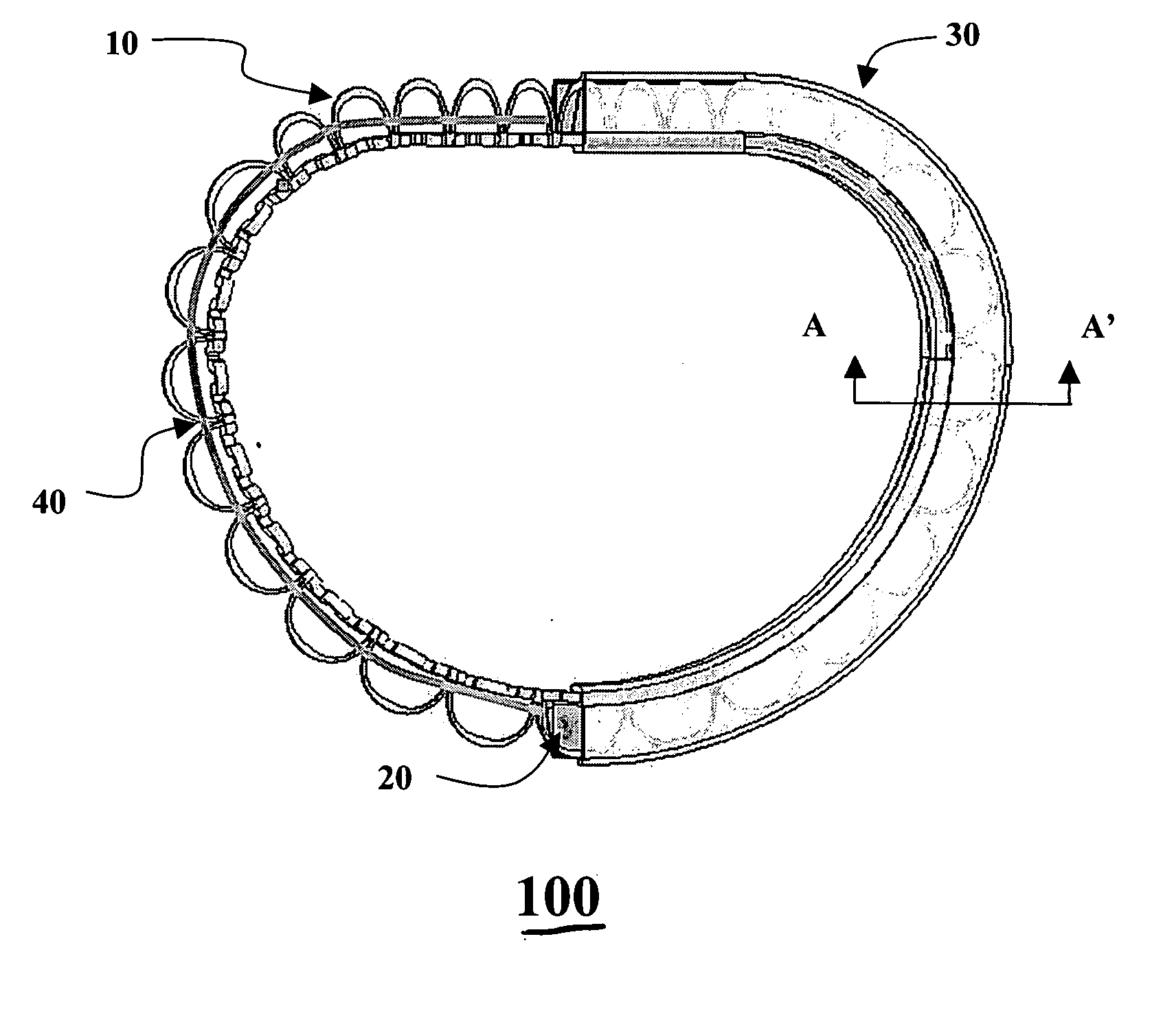
[0011] According to the present invention, the ring prosthesis provides suitable flexibilities / stiffness three-dimensionally at various points about the circumference of an associated heart valve, and is shaped proportionally to fit about the annulus of the associated heart valve. The ring prosthesis also provides a certain flexibility to conform to the natural non-planar shape of the annulus (e.g., saddle shape for mitral valve surface) with or without preformation of the ring prosthesis. The prosthesis can also be used as an artificial annulus for further valve anchoring.

Problems solved by technology

Unfortunately, uniformly rigid annuloplasty rings do not conform to the natural non-planar shape of the human valve annulus.
One problem associated with the annuloplasty rings of the prior art is that when such annuloplasty rings are implanted into children or adolescents (such as pediatric patients with CVA or RVD), the subsequent growth of the patient may render the annuloplasty ring too small for its intended function, thereby abnormally constricting the annulus.
However, the tissue of the heart valve annulus grows into the fabric of the annuloplasty ring by design, so that the annuloplasty ring is soon embedded in living tissue, thereby making such replacement surgery problematic.

Method used


Image

  • Valvular support prosthesis
  • Valvular support prosthesis
  • Valvular support prosthesis

Examples


Embodiment Construction

[0023] The following detailed description is of the best presently contemplated modes of carrying out the invention. This description is not to be taken in a limiting sense, but is made merely for the purpose of illustrating general principles of embodiments of the invention. The scope of the invention is best defined by the appended claims.

[0024] Inasmuch as the human mitral valve is far more likely to require repair than the tricuspid, aortic and pulmonary valves, the description of the present invention herein will be based on the repair of a mitral valve. However, the same principles discussed herein in connection with the repair of a mitral valve also apply to the repair of all other heart valves.

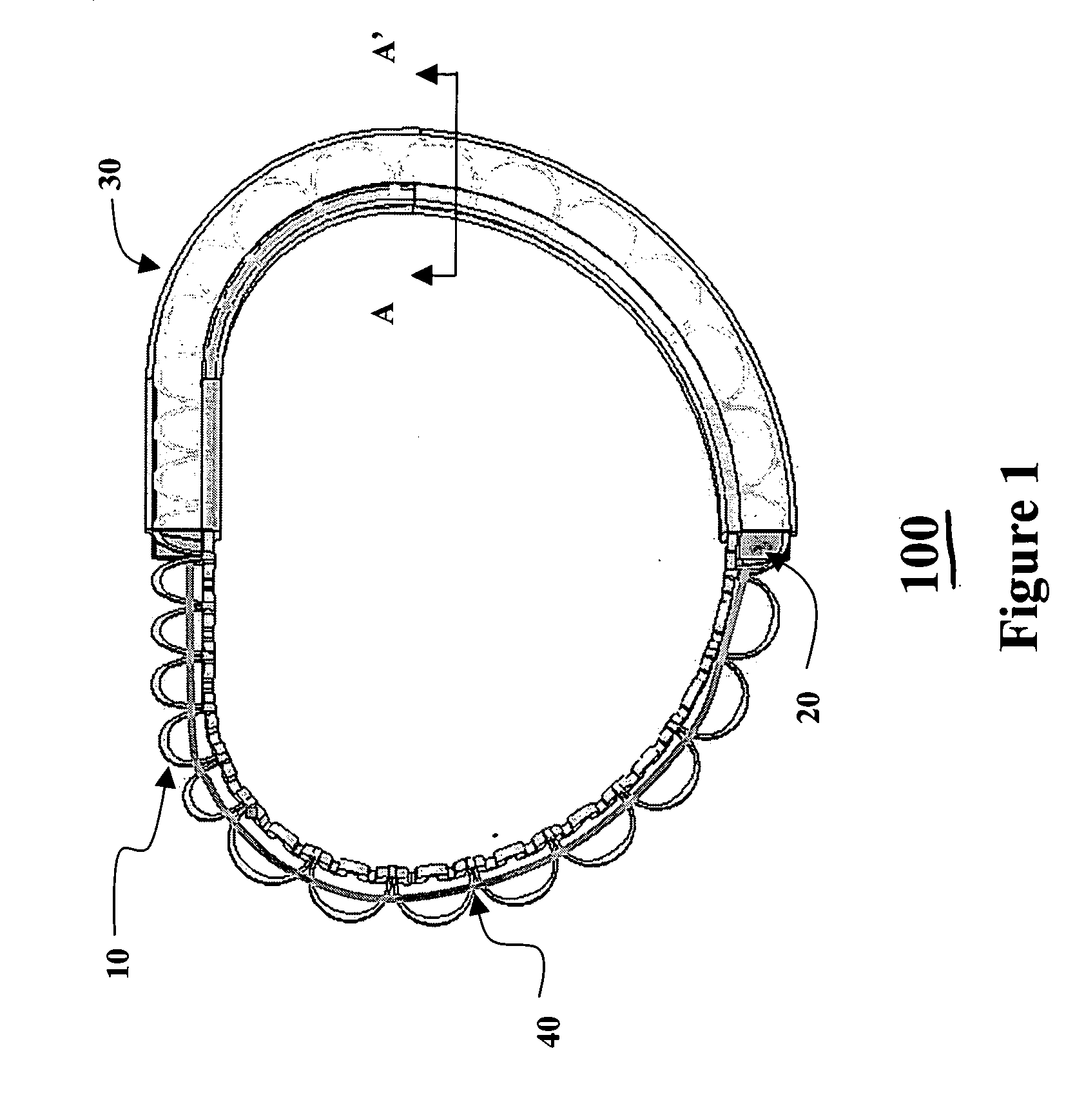
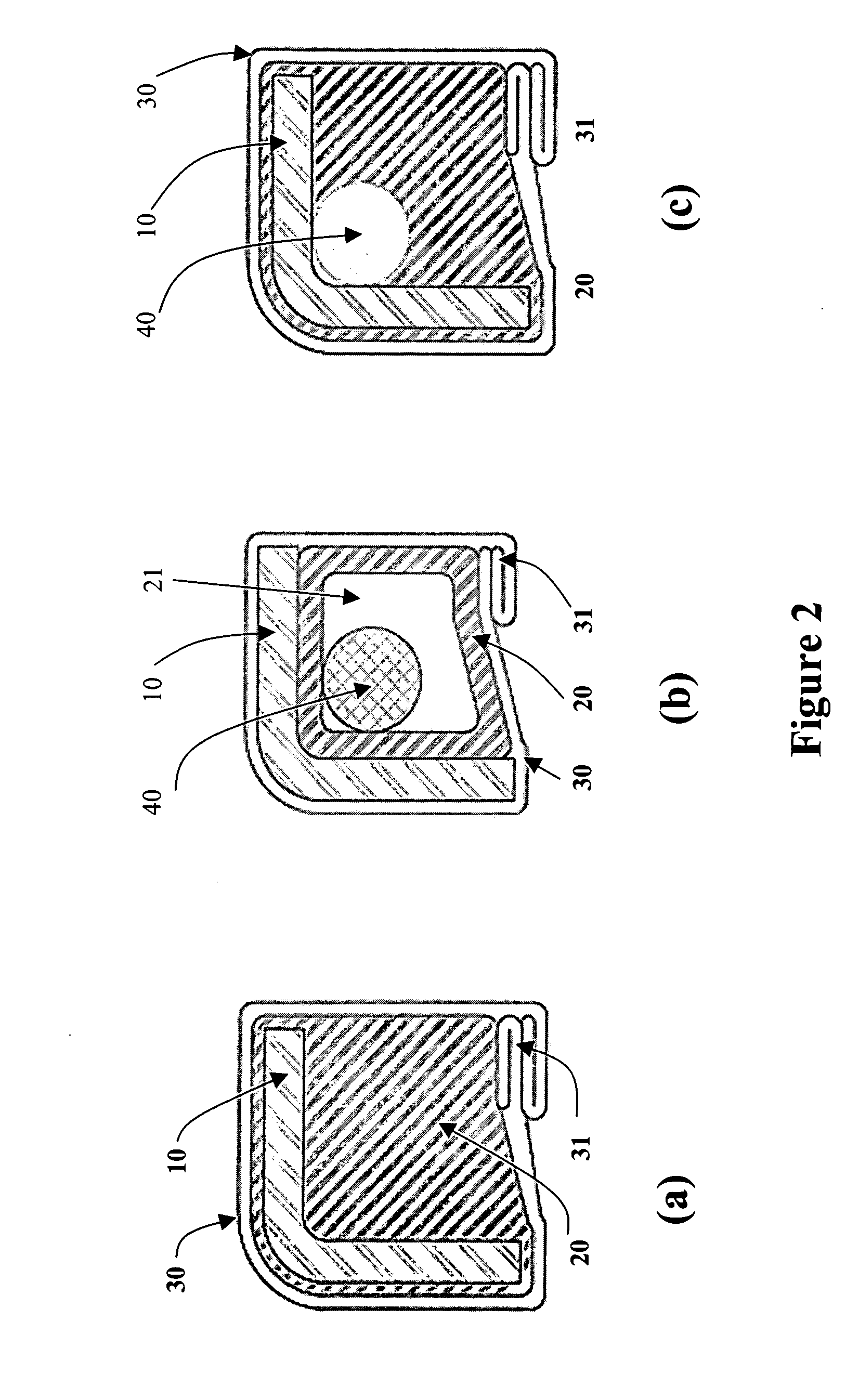
[0025]FIGS. 1-3 illustrate a ring prosthesis 100 according to one embodiment of the present invention. The ring prosthesis 100 is illustrated herein as an annuloplasty ring 100. The annuloplasty ring 100 can be made of a single inner frame member 10 that is covered by a suture-permea...


PUM


Abstract

A ring prosthesis provides suitable flexibilities / stiffness three-dimensionally at various points about the circumference of an associated heart valve, and is shaped proportionally to fit about the annulus of the associated heart valve. The ring prosthesis also provides a certain flexibility to conform to the natural non-planar shape of the annulus (e.g., saddle shape for mitral valve surface) with or without preformation of the ring prosthesis. The prosthesis can also be used as an artificial annulus for further valve anchoring.

Description

BACKGROUND OF THE INVENTION [0001] 1. Field of the Invention [0002] The present invention relates to a support prosthesis for use in medical applications, and in particular, to an annuloplasty ring that is adapted for use in supporting a heart valve. [0003] 2. Description of the Prior Art [0004] Annuloplasty rings for use as heart valve prostheses are well known in adult patients. Most such annuloplasty rings are substantially planar. Recently, an interest in non-planar (e.g., saddle-shaped) annuloplasty rings has developed. The conventional non-planar annuloplasty rings tend to be substantially rigid throughout the annuloplasty ring. Unfortunately, uniformly rigid annuloplasty rings do not conform to the natural non-planar shape of the human valve annulus. As a result, these uniformly rigid annuloplasty rings do not move with the valve tissue, thereby increasing the stress to the leaflet or surrounding tissue. [0005] In addition, many patients who suffer from disfunction of the mit...

Claims


Application Information

Patent Timeline
IPC IPC(8): A61F2/24
CPCA61F2/2409A61F2/2448A61F2250/0018A61F2002/8483
Inventor YANG, JUNZENG, FRANK M.
Owner YANG JUN
Learn More