Eureka AIR delivers breakthrough ideas for toughest innovation challenges, trusted by R&D personnel around the world.

Coordinated shared storage architecture

Active Publication Date: 2006-09-14
NETWORK APPLIANCE INC
View PDF53 Cites 63 Cited by
  • Summary
  • Abstract
  • Description
  • Claims
  • Application Information

AI Technical Summary

Benefits of technology

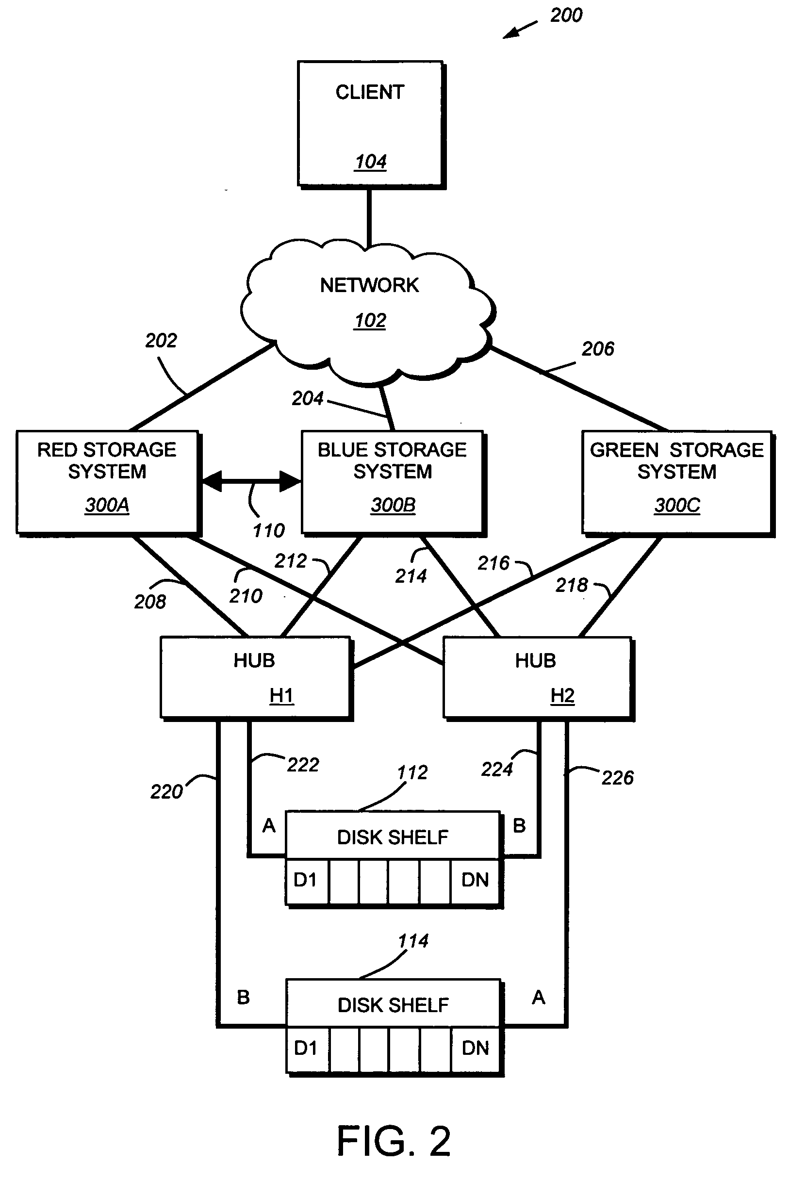
[0017] The present invention overcomes the disadvantages of the prior art by providing a novel coordinated shared storage architecture that permits the amortization of cost of the spares over any number of the storage systems and enables improvements to a number of storage system operations. The coordinated shared storage architecture comprises a plurality of storage systems disk shelves via a plurality of intermediate network devices, such as hubs. Each storage system includes a storage operating system having a target device driver module. The target device driver module permits the storage system to function as a SCSI target and thereby receive and process commands directed to it from other storage systems.
[0018] The coordinated shared storage architecture provides variety of useful applications or features within in a storage system environment that cannot be provided in a conventional storage system environment. For example, the novel architecture provides the ability to dynamically increase various capabilities of the storage system environment, such as efficiently enabling an additional storage system to be interconnected with the intermediate network devices. This feature of the invention enables all disks in the storage system environment to be serviced by the newly added storage system. Similarly, disk shelves can be efficiently added to the environment by simply connecting them to one or more intermediate network devices. Once connected, the storage space provided by the disks of the shelves is available to all of the storage systems of the environment.

Problems solved by technology

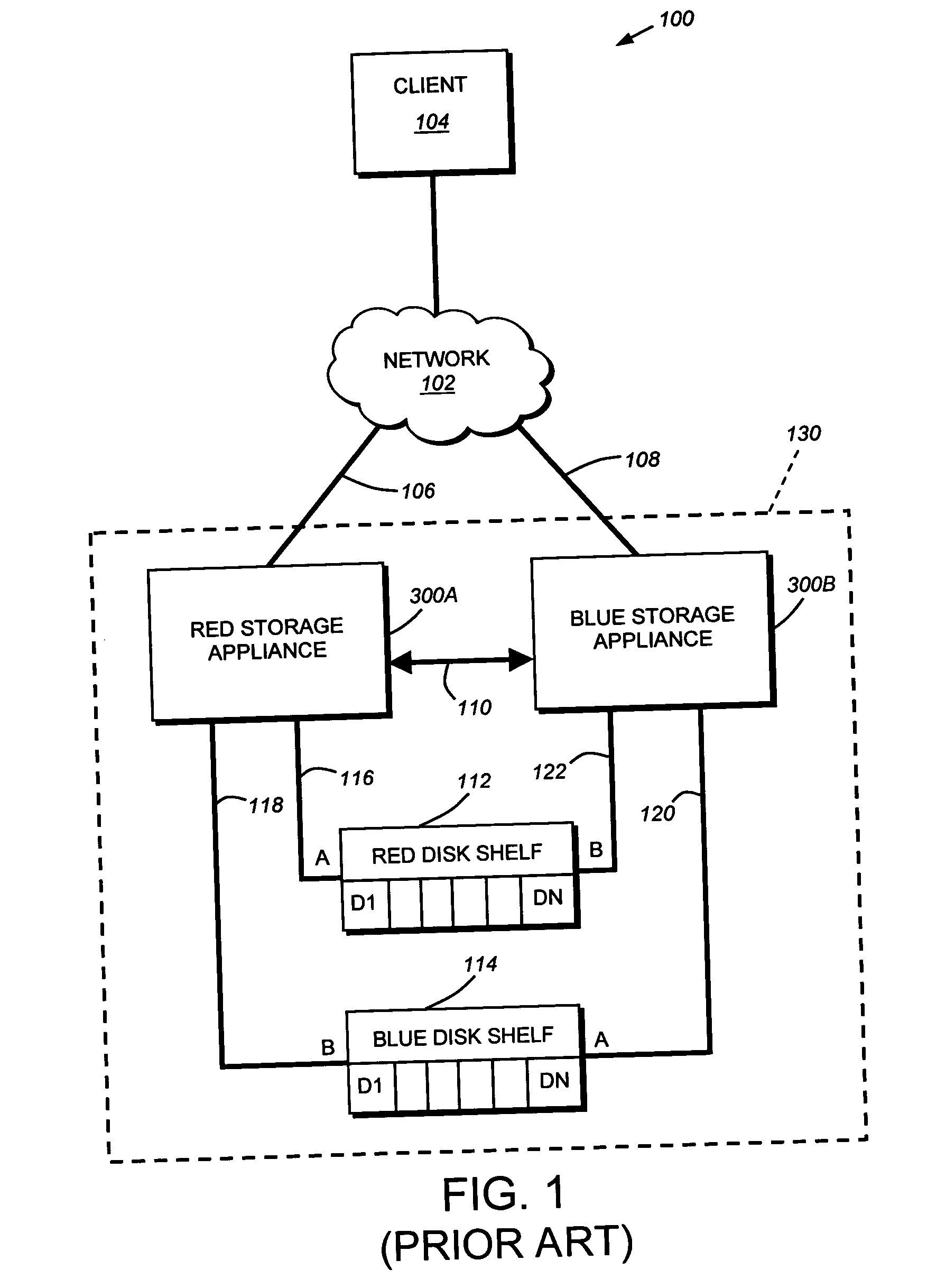
One such disadvantage is that the cost of a spare disk is typically only amortized over the two storage systems of a cluster.
In an environment having any number of clusters, the limitation may prove costly.
That is, if a single cluster exhausts its spares, data may be lost even though other spares exist in the overall storage system environment.
Secondly, load balancing may be performed among only the disks and / or storage systems operatively interconnected with the disk shelves.
Another disadvantage is that conventional storage system clusters do not scale easily.
Moreover, transfer of disk ownership may be required in response to such “manual” cluster scaling, thus necessitating physical movement of disks in a disk shelf among cluster pairs.

Method used


Image

  • Coordinated shared storage architecture
  • Coordinated shared storage architecture
  • Coordinated shared storage architecture

Examples


Embodiment Construction

A. Clustered Storage System Environment

[0030]FIG. 2 is a schematic block diagram of an exemplary network environment 200 in which the principles of the present invention are implemented. The environment 200 comprises a network cloud 102 coupled to one or more clients 104. The client 104 may be a general-purpose computer, such as a PC or a workstation, or a special-purpose computer, such as an application server, configured to execute applications over an operating system that includes block access protocols. A Red Storage System 300A, Blue Storage System 300B and Green Storage System 300C are also connected to the cloud 102. These storage systems, described further below, are illustratively embodied as storage appliances configured to control storage of and access to interconnected storage devices, such as disks residing on disk shelves 112 and 114.

[0031] The Red, Blue and Green storage systems 300 A, B, C are connected to the network 102 via “front-end” data pathways 202, 204, 206...


PUM


Abstract

The present invention provides a novel coordinated shared storage architecture that permits the amortization of cost of the spares over any number of the storage systems and enables improvements to a number of storage system operations. The coordinated shared storage architecture comprises a plurality of storage systems disk shelves via a plurality of intermediate network devices, such as hubs. Each storage system includes a storage operating system having a target device driver module. The target device driver module permits the storage system to function as a SCSI target and thereby receive and process commands directed to it from other storage systems.

Description

CROSS-REFERENCE TO RELATED APPLICATIONS [0001] The present application claims the benefit of U.S. Provisional Patent Application Serial No. (Atty. Docket No. 112056-0197), which was filed on Jan. 27, 2005, by Anthony Aiello for a COORDINATED SHARED STORAGE ARCHITECTURE and is hereby incorporated by reference. RELATED APPLICATION [0002] The present application is related to U.S. patent application Ser. No. 112056-0198U, entitled SYSTEM AND METHOD FOR DISTRIBUTING ENCLOSURE SERVICES DATA TO COORDINATE SHARED STORAGE, by Randy Thelen, et al, the contents of which are hereby incorporated by reference.FIELD OF THE INVENTION [0003] The present invention relates to storage systems and, in particular, to a coordinated shared storage architecture for use with a plurality of storage systems. BACKGROUND OF THE INVENTION [0004] A storage system is a computer that provides storage service relating to the organization of information on writeable persistent storage devices, such as memories, tapes...

Claims


Application Information

Patent Timeline
IPC IPC(8): G06F12/14G06F12/00
CPCG06F3/0607G06F3/0632G06F3/0635G06F3/067H04L67/1097G06F11/2092G06F11/2094G06F2206/1012G06F2211/1028G06F11/1092
Inventor AIELLO, ANTHONY F.ASTER, RADEKTHELEN, RANDALKONG, GEORGE
Owner NETWORK APPLIANCE INC
Why Eureka
Eureka Blog
Learn More