
System and method for depositing a metal to form a three-dimensional part

a three-dimensional part and metal technology, applied in the field of 3d printing, can solve the problems of not being able to withstand high stress or high temperature, the temperature limitation of these materials remains, and the material limitations of sla printers are different, so as to reduce the time per part, reduce the cost of the machine, and reduce the risk of handling. , the effect of reducing the time per par

Active Publication Date: 2021-05-04
MITSUBISHI ELECTRIC RES LAB INC
View PDF22 Cites 0 Cited by
  • Summary
  • Abstract
  • Description
  • Claims
  • Application Information

AI Technical Summary

Benefits of technology

[0020]The embodiments of the invention provide a system and method for 3D printing metals with a precision and full density of the DMLS process but at a much lower cost, by increasing the speed of production, improving the as-printed surface finish, and using a feedstock with much lower costs of production and ease of handling.
[0022]Because the feedstock is metal wire, handling hazards are greatly reduced. Because the wire feed is placed with precision only where material needs to be deposited, there is no wasted feedstock, and because a large fraction of the heating energy is produced by ohmic heating of the wire, the wire heats uniformly in bulk, rather than only at the surface as with laser-only or electron-beam-only heating, so effectively the system can deposit material much more rapidly, on the order of a kilogram per hour, which decreases the time per part, and amortizes the cost of the machine much more rapidly, producing a much less expensive part.

Problems solved by technology

The limitation of such printers is that the final result is plastic, and as such cannot withstand high stresses or high temperatures.
Similarly, the operating temperature limitation for most polymers extrudable by FDM printers is typically 20 degC, or more, well below the glass transition temperature of the polymer, to avoid high creep rates.
SLA printers have different material limitations given that the transition of the feed material from liquid to solid is triggered by ultraviolet light, or intense blue light.
However, the temperature limitations of these materials remain.
Given the material limitations of both strength and temperature tolerance, polymer 3D printed parts cannot be used in many situations, such as engines, fuel systems, or many biological implant systems.
Then, the plastic part is used to produce a negative mold, often destructively, as in lost-wax or lost-plastic methods.
Unfortunately, this process requires significant time and a fully capable foundry facility to produce the parts, which are basically no different than the millenia-old lost wax process, and with the same limitations on molding and precision.
The resulting layers, sintered together, are termed a “green part”, and are quite fragile.
That process is limited to facilities that support a bronze foundry, and to produce parts that are not of one alloy (the parts are partially stainless steel and partially bronze or brass.
They are also subject to self-produced electrolytic corrosion.
), and so a metal machining facility may still be appropriate, which is a disadvantage compared to polymer 3D printing systems that usually produce ready-to-use parts.
A second disadvantage of full-density DMLS is cost.
This lack of speed translates into a long time to print, which translates directly into a high cost per part to amortize the up-front cost of the physical machine and the slow production available.
A third disadvantage of DMLS is that the feed powder is only partially reclaimable.
Some DMLS manufacturers simply preclude the re-use of feedstock powder unilaterally because of the risk of a too-large particle being caught by the doctor blade and plowing a line without powder into the thin top layer, causing a void in the part.
Finally, DMLS feed materials are extremely finely divided metal powders, and as such are potentially hazardous (such as inhalation hazard, possible flammability or even pyrophoric hazard), as well as requiring special handling, such as keeping the powder under inert gas such as argon to prevent any oxidation forming during transport and storage.
Disadvantages are that because the system uses an arc, a large amount of spatter is present and the surface finish is no better than what one would expect in an arc-welded joint—that is, surface roughness is on the order of a couple of millimeters, not 10-100 microns as with other 3D printing technologies.
LMD-w is unfortunately process-limited to relatively large diameter wires (0.028 inch-0.7 mm) due to thermal issues as described below which sets a rather large feature size and relatively coarse printing with rough final surfaces.
Increasing the electron beam accelerating voltage causes a deeper penetration of the electron beam (a useful property of electron beam weld melt zones is that they can be as much as three to five times deeper than their width), but this is detrimental during additive manufacturing as it will cause a vertical wall to slump downward due to gravitation and to form a blobby surface due to surface tension.

Method used


Image

  • System and method for depositing a metal to form a three-dimensional part

Examples


Embodiment Construction

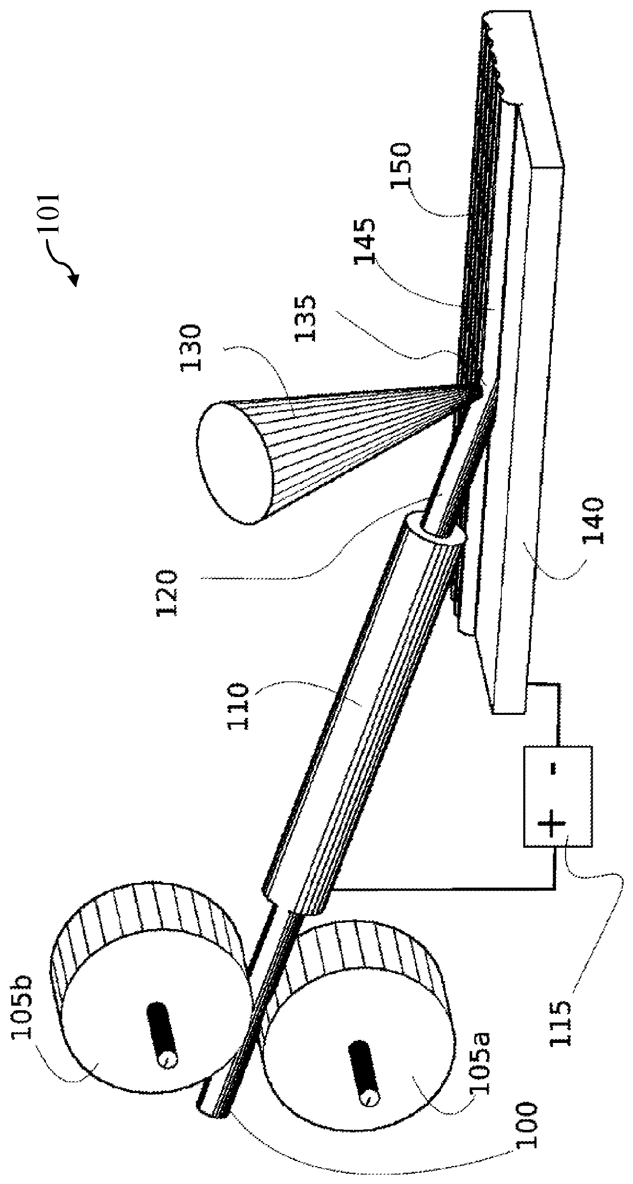
[0024]FIG. 1 is an elevated side view of the system according to embodiments of the invention. The system 101 includes feedstock wire 100 is moved by drive rollers 105a and 105b. The feedstock wire 100 passes through the wire guide and electrical contact tube 110. A power supply 115 supplies a controlled amount of current through the contact tube 110, the feedstock wire 100, through a workpiece 140, with the current returning to the power supply 115.

[0025]The required amount of current for a wire 0.006 inches (about 150 microns) is very moderate—only about six to nine amperes, at a nominal 1 Kg / hour deposition rate for steel, and far, far below the tens to hundreds of amperes that would be used for processes such as MIG welding or MIG cladding.

[0026]The ohmic heating supplied in section 120 of the feedwire 100 is intentionally insufficient to melt the wire. Instead, the wire 100 continues to a laser beam 130 supplied by a laser 130, focused at the intersection of the hot wire 100 an...


PUM

PropertyMeasurementUnit
diameteraaaaaaaaaa
circuit voltageaaaaaaaaaa
ultimate tensile strengthsaaaaaaaaaa

Abstract

A system and method depositing metal to form a three-dimensional (3D) part on a substrate. A wire is moved relative to a location on the substrate while a laser heats a proximal end of the wire at the location using a laser beam. The laser causes the wire and substrate to reach a melting point of the wire to fuse the wire at the location on the substrate. The wire can be preheated by passing a current through the wire.

Description

FIELD OF THE INVENTION[0001]This invention relates generally to 3D printing, and more particularly to a combined laser and ohmic heating system and method to deposit metal to produce a metal part from wire feedstock.BACKGROUND OF THE INVENTION[0002]Three-dimensional printing (3D printing) is now a well-known technology, which can be used for rapid prototyping, and for constructing fully functioning parts. 3D printing is also known as “additive manufacturing,” because unlike most machine tool operations, undifferentiated feed material is repeatedly added to construct a part using successive layers of a material such as plastic or metal. This is different from traditional machine-shop operations, such as sawing, drilling, turning, and milling, which removes material in successive layers until only the desired material remains.[0003]Most common and inexpensive 3D printers produce the desired parts using a plastic material, by either fused deposition modeling (FDM), i.e., precision extr...

Claims


Application Information

Patent Timeline
Patent Type & Authority Patents(United States)
IPC IPC(8): B23K26/346B23K26/14B23K26/342B23K26/08B33Y10/00B33Y30/00
CPCB23K26/346B23K26/083B23K26/1423B23K26/342B33Y10/00B33Y30/00
Inventor YERAZUNIS, WILLIAM SBARNWELL, III, JOHN CVETTERLING, WILLIAM T
Owner MITSUBISHI ELECTRIC RES LAB INC
Learn More