Nozzle device and hygienic washing device

a technology of hygienic washing and nozzle, which is applied in the direction of water installations, baths, constructions, etc., can solve the problems of not being able to wash the parts of the private parts of the human body, affecting the cleanliness of the nozzle, so as to save space, the temperature of the washing water is not lowered, and the power consumption is kept to a minimum

Inactive Publication Date: 2006-09-21
PANASONIC CORP
View PDF15 Cites 29 Cited by
  • Summary
  • Abstract
  • Description
  • Claims
  • Application Information

AI Technical Summary

Benefits of technology

[0114] In this case, the washing water is heated while being caused to flow by the instantaneous heating device. Consequently, the washing water is heated only when the sanitary washing apparatus is employed, thereby making it possible to keep power consum

Problems solved by technology

However, the dirt that has adhered to a step, a groove, a clearance, and so forth on a surface of the nozzle is not easily cleaned.
In the above-mentioned conventional nozzle device, however, the washing water sprayed from the water discharge hole encou

Method used


Image

  • Nozzle device and hygienic washing device
  • Nozzle device and hygienic washing device
  • Nozzle device and hygienic washing device

Examples


first embodiment

[0171] (1) First Embodiment

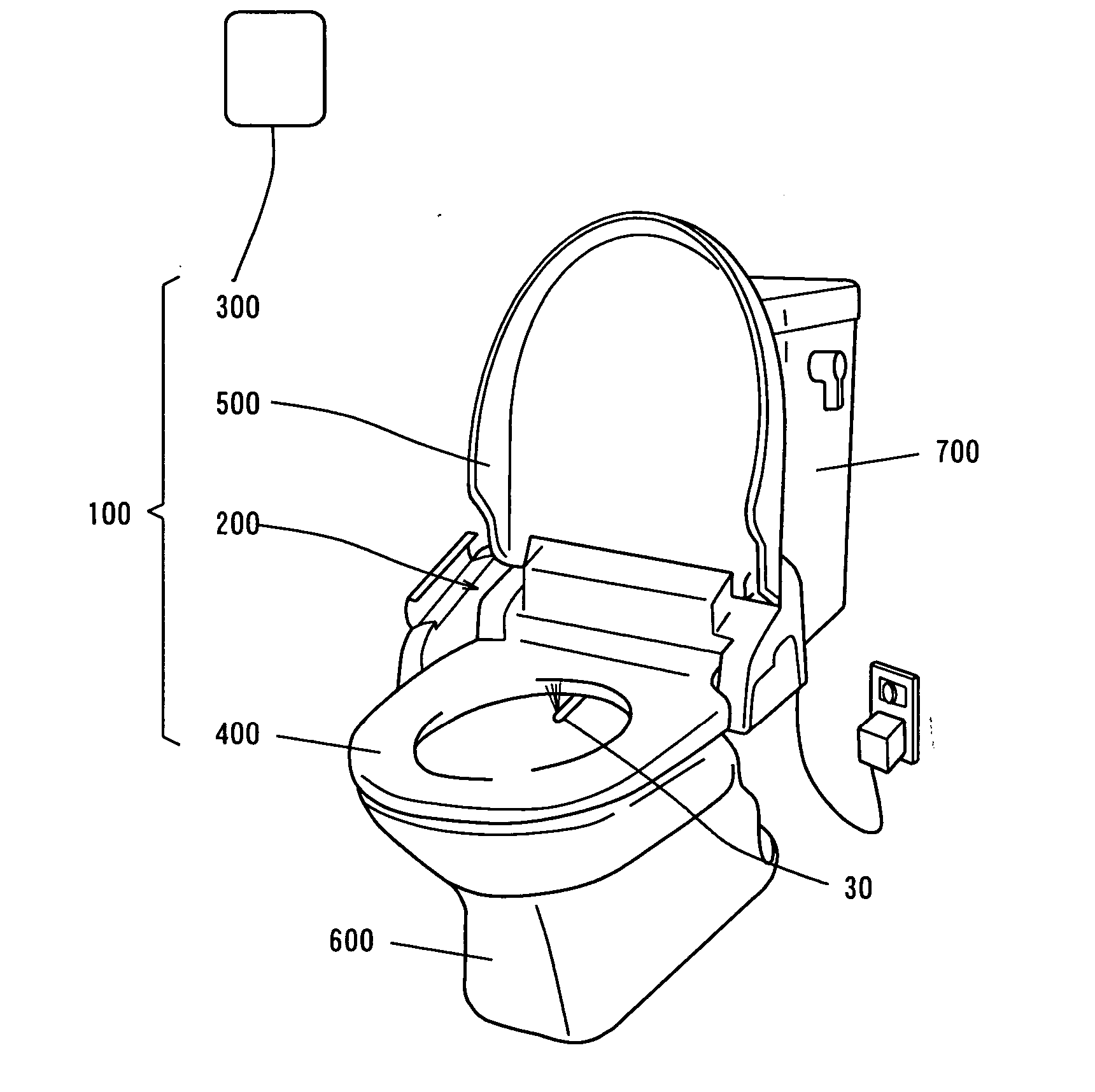
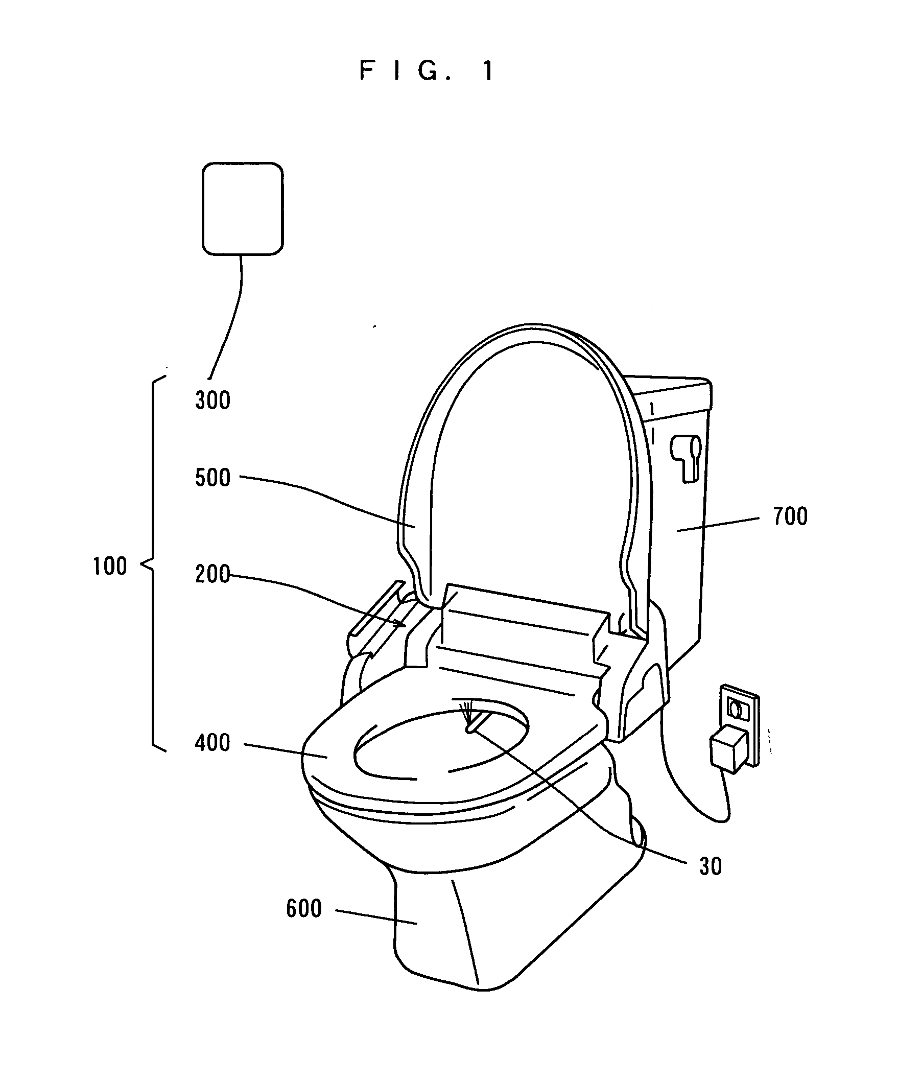
[0172]FIG. 1 is a perspective view showing a state where a sanitary washing apparatus according to a first embodiment of the present invention is mounted on a toilet bowl.

[0173] As shown in FIG. 1, a sanitary washing apparatus 100 is mounted on a toilet bowl 600. A tank 700 is connected to a tap water pipe, and supplies washing water to the toilet bowl 600.

[0174] The sanitary washing apparatus 100 comprises a main body 200, a remote control device 300, a toilet seat 400, and a cover 500.

[0175] The toilet seat 400 and the cover 500 are attached to the main body 200 so as to be capable of being opened or closed. Further, the main body 200 is provided with a washing water supply mechanism including a nozzle unit 30, and contains a controller. The controller in the main body 200 controls the washing water supply mechanism on the basis of a signal transmitted by the remote control device 300, as described later. The controller in the main body 200 also contr...

second embodiment

[0295] (Second Embodiment)

[0296] The difference of the configuration of a piston 20a in a posterior nozzle 1 in a second embodiment from the configuration of the piston 20 in the posterior nozzle 1 in the first embodiment, together with the function and effect thereof, will be described while referring to the following drawings.

[0297]FIG. 22(a) is a perspective view of a piston in a posterior nozzle, and FIG. 22(b) is an exploded perspective view of a washing water supply portion in the piston. FIG. 23 is an exploded perspective view of the piston in the posterior nozzle, FIG. 24(a) is a side view of the piston 20a, and FIG. 24(b) is a plan view of the piston 20a.

[0298] As shown in FIG. 22(a), the piston 20a comprises a nozzle cover 401 and a washing water supply portion 420. In FIG. 22(a), the nozzle cover 401 is indicated by a one-dot and dash line. The washing water supply portion 420 comprises a two-flow path pipe 402c, a one-flow path pipe 403c, and a flow path merger 404h.

[...

third embodiment

[0349] (Third Embodiment)

[0350] The difference of the configuration of a main body in a sanitary washing apparatus according to a third embodiment from the configuration of the main body 200 in the sanitary washing apparatus according to the first embodiment, together with the function and effect thereof, will be described while referring to the following drawings.

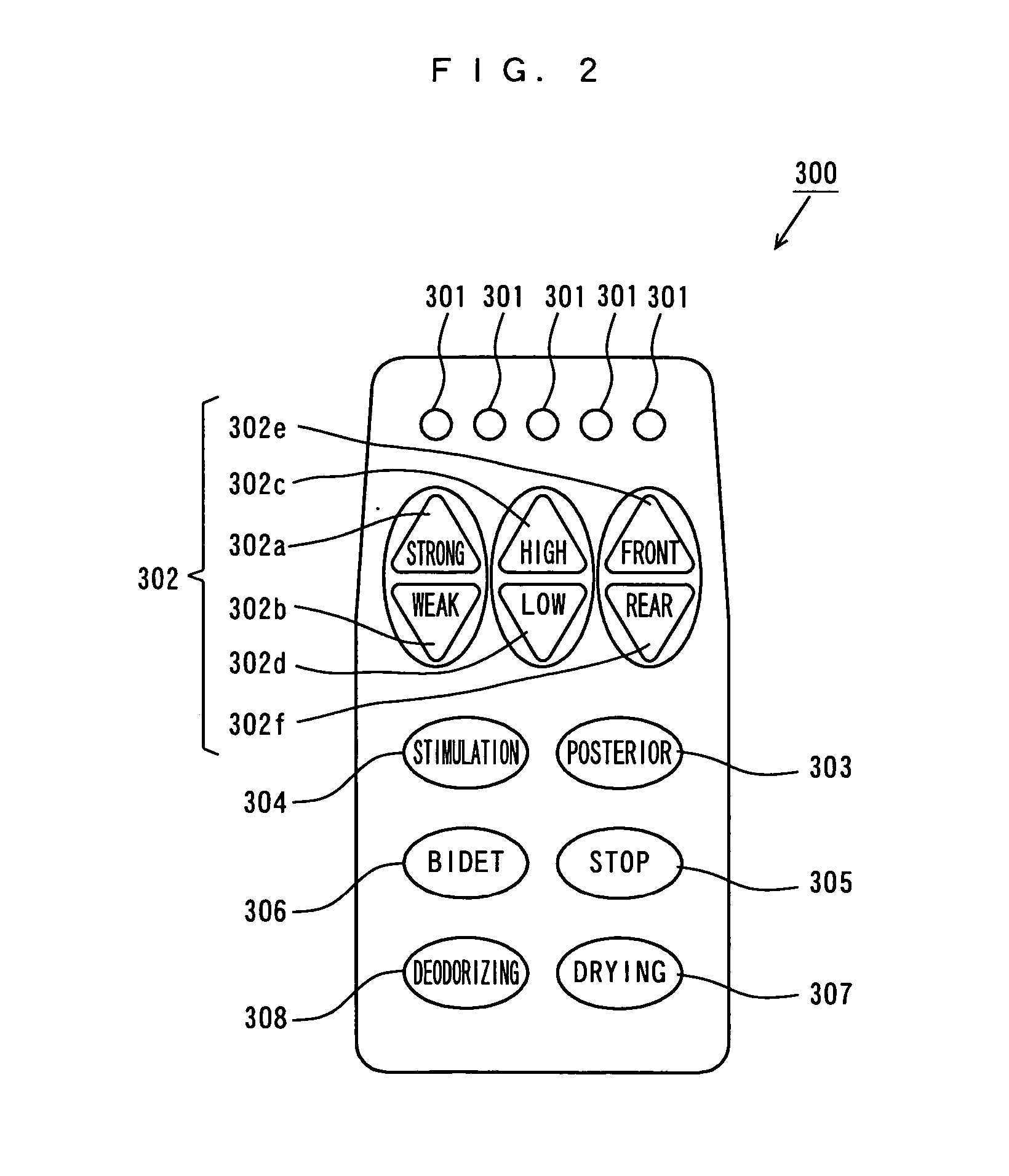
[0351]FIG. 29 is a schematic view showing another example of the remote control device 300 shown in FIG. 1.

[0352] As shown in FIG. 29, the remote control device 300 differs from the remote control device 300 shown in FIG. 1 according to the first embodiment in that it further comprises a nozzle cleaning switch 309 and a nozzle high-temperature cleaning switch 310.

[0353] A nozzle unit 30 is cleaned using washing water by pressing the nozzle cleaning switch 309, while being cleaned using washing water heated at high temperature by pressing the nozzle high-temperature cleaning switch 310. The details of the cleaning operat...


PUM


Abstract

Since the inner diameter of a flow-contracting portion continuously decreases toward a cylindrical swirl chamber, the velocity of flow of washing water flowing in the flow-contracting portion continuously rises. Since the inner diameter of the flow-contracting portion continuously decreases toward a spray hole, the velocity of flow of the washing water flowing in the flow-contracting portion continuously rises. Washing water supplied to one of flow paths in a two-flow path pipe is supplied to a flow path merger through a one-flow path pipe. The washing water supplied to the other flow path in the two-flow path pipe is supplied to the flow path merger after passing through a space between the one-flow path pipe and a nozzle cover. Washing water sprayed from a nozzle cleaning hole flows out of an opening at a front end of a nozzle cleaning cylinder along an outer peripheral surface of a piston while being spirally swirled in a space between an inner wall of the nozzle cleaning cylinder and the outer peripheral surface of the piston. A position fixing member having a curved shape along an inner surface at a front end of the nozzle cover is formed at a front end of the flow path merger. While a posterior nozzle moves from a forward position to a backward position, dispersed spiral flow and linear flow are alternately sprayed.

Description

TECHNICAL FIELD [0001] The present invention relates to a sanitary washing apparatus that washes the private parts of the human body. BACKGROUND ART [0002] In sanitary washing apparatuses that wash the private parts of the human bodies, washing water is sprayed from nozzles projecting to positions of washing from the positions where nozzle devices are accommodated to do washing. [0003] In such nozzle devices, front ends of nozzles approach the private parts of the human bodies at the time of washing operations so that the washing water is sprayed. In this case, dirt may, in some cases, adhere to the nozzles in the case of washing. Therefore, various types of functions for cleaning the nozzles have been proposed. [0004] Examples of the functions of cleaning the nozzles include cleaning a nozzle cleaning nozzle (see JP-A-11-193567, for example). In this case, dirt that has adhered to a nozzle itself can be cleaned by causing washing water to flow through the nozzle before or after a w...

Claims


Application Information

Patent Timeline
IPC IPC(8): E03D9/08A47K3/20A47K4/00B05B1/34B05B15/10B05B15/74
CPCE03D9/08B05B1/3426B05B7/0408B05B15/74
Inventor KOGA, RYOUICHIARIKAWA, TOMIOENGUCHI, ITARUKAWAMOTO, YASUHIRO
Owner PANASONIC CORP
Why Eureka
Try Eureka