Method for cooling a liquid-cooled friction clutch and liquid-cooled friction clutch

a technology of friction clutch and liquid cooling, which is applied in the direction of fluid actuated clutches, clutches, non-mechanical actuated clutches, etc., can solve the problem of unusable potential energy

Inactive Publication Date: 2006-09-21
LUK LAMELLEN & KUPPLUNGSBAU BETEILIGUNGS KG
View PDF9 Cites 8 Cited by
  • Summary
  • Abstract
  • Description
  • Claims
  • Application Information

AI Technical Summary

Benefits of technology

[0026] Furthermore, it is advantageous to implement the flow sampling component in such way that it has a surface pressing tangentially against the coolant liquid ring and is bent away from the coolant liquid ring on its end directed

Problems solved by technology

In clutches having a vertical axis of rot

Method used


Image

  • Method for cooling a liquid-cooled friction clutch and liquid-cooled friction clutch
  • Method for cooling a liquid-cooled friction clutch and liquid-cooled friction clutch
  • Method for cooling a liquid-cooled friction clutch and liquid-cooled friction clutch

Examples


Embodiment Construction

[0037] The present invention is explained in the following on the basis of a double clutch, as is used for parallel manual shift transmissions. It is obvious that the present invention may also be used for other types of friction clutches having only one clutch unit, for example.

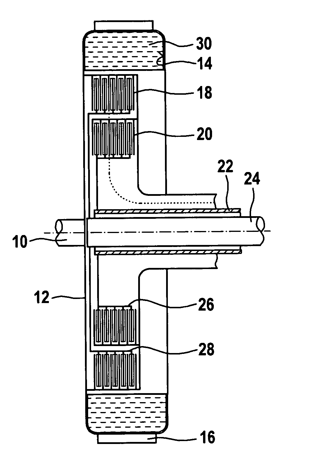
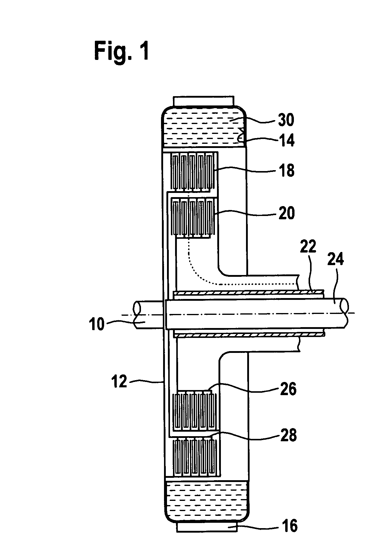
[0038] According to FIG. 1, a driveshaft 10, which is driven by an engine (not shown), is rigidly connected to a clutch housing 12, which ends radially on the outside in a trough 14, which is open radially on the inside and is circular overall. The radial external side of the trough 14 is provided with blades 16. A radial external lamellar packet 18 and a radial internal lamellar packet 20 are connected rotationally fixed to the clutch housing 12 via a carrier. A hollow output shaft 22, in which a further output shaft 24 is mounted coaxially thereto, is mounted on the clutch housing 12 and / or the carrier of the lamellar packet 18 and 20 connected rigidly thereto. A radial internal lamellar packet 26 is conn...


PUM


Abstract

A liquid-cooled friction clutch contains at least one lamella, which is connected rotationally fixed to a driveshaft, at least one lamella, which is connected rotationally fixed to an output shaft, these lamellae being able to be pressed mutually against one another and being positioned inside a clutch housing connected rotationally fixed to the driveshaft, and a coolant liquid return line, which leads from an area radially outside the lamellae to an area radially inside the lamellae and returns coolant liquid after its radial flow along the lamellae from the radial external area into the radial internal area, an end area of the return line being implemented as a scoop tube having an intake opening which is immersed radially outside the lamellae in a coolant liquid ring rotating together with the clutch housing and returns the coolant liquid into the area radially inside the lamellae without flowing through a pump driven by external force.

Description

CROSS REFERENCE TO RELATED APPLICATION [0001] This patent application claims priority of German Patent Application No. 10 2005 012 034.2, filed Mar. 16, 2005, which application is incorporated herein by reference. FIELD OF THE INVENTION [0002] The present invention relates to a method for cooling a liquid-cooled friction clutch. Furthermore, the present invention relates to a liquid-cooled friction clutch. BACKGROUND OF THE INVENTION [0003] The heat arising during slip on lamellae and / or friction disks, which transmit torque, is dissipated in liquid-cooled friction clutches using coolant liquid. This coolant liquid, which may be used simultaneously for lubricating bearings of the clutch or even of a transmission, circulates in a loop, within which it flows through a cooler. It is expedient to regulate the quantity of coolant liquid supplied to the clutch and flowing between the friction disks depending on the driving condition. During driving, a minimum volume flow is required to di...

Claims


Application Information

Patent Timeline
IPC IPC(8): F16D13/72
CPCF16D13/72F16D2021/0661F16D25/10
Inventor ARNOLD, JOHANNESREIK, WOLFGANGAGNER, IVONOEHL, OLIVER
Owner LUK LAMELLEN & KUPPLUNGSBAU BETEILIGUNGS KG
Why Eureka
Try Eureka