Energy network using electrolysers and fuel cells

a fuel cell and electrolyte technology, applied in the direction of fuel cells, ac network voltage adjustment, gas/liquid distribution and storage, etc., can solve the problems of low efficiency of gaseous hydrogen, lack of fuel supply infrastructure, no large-scale pipeline delivery infrastructure for hydrogen, etc., to reduce power levels, reduce emissions, and reduce efficiency

Inactive Publication Date: 2006-09-21
STUART ENERGY SYST
View PDF51 Cites 51 Cited by
  • Summary
  • Abstract
  • Description
  • Claims
  • Application Information

AI Technical Summary

Benefits of technology

[0065] Locating hydrogen power regeneration at locations to distribute operating reserves and improve system reliability to avoid need for committing larger units of generation;
[0067] Providing a supplemental load to permit base load plants to operate at their optimum efficiency and lowest emissions during periods of low demand.
[0068] The network operator could also work closely with the other power generators on the public grid to make power purchases bilaterally to reduce emissions through demand management of specific generators such as natural gas fired generation where a significant drop in efficiency occurs when power levels are reduced and hence a significant increase occurs in specific emissions (emission gm per kWh). By increasing loads through hydrogen production the generator can be more efficient and hence produces lower specific emissions. In this way the network can also act to improve the efficiency of the public grid.
[0069] These actions could be formally contracted by selling ancillary services to the grid. Because the network can adjust energy flows between captive power plants and hydrogen production in a very precise fashion and on a “real-time” basis the system can provide short-term operating reserves to the grid and even “spinning reserves” by making a certain proportion of the demand for fuel production a “responsive” load. In this way, in the event of outage of a generator or transmission line and the network is contracted to provide operating reserves, the network controller would be notified and would turn down the rate of hydrogen production to make power available as required. Similarly in dynamic control, when load is picking up at the beginning of high demand periods or during periods when load is dropping off, the network can operate as a variable power generator to facilitate the ramp up of power plants. For some forms of generation that are currently used, such as coal powered generators, this will reduce start up times and increase the efficiency of operation, resulting in lower specific emissions. Where the electrical load is large enough, the network could be used to dynamically adjust load in the electrical network to improve efficiency and reduce cost through potentially maintaining a higher level of control than otherwise available by adjusting output of conventional power generators. The tighter control of the grid will result in efficiency improvement benefits which will accrue to the network and which also lower specific emission rates for the grid. These actions could be enhanced by regenerative systems that can be part of the network through “hydrogen energy stations” which incorporate power regeneration from hydrogen fuel with hydrogen production.
[0070] The list of ancillary services provided by the Hydrogen Network could include: “spinning” type reserves (<1 minute dispatch time), operating reserves, emission reductions (i.e. air quality emergency) and to some degree generator control as well as relieving local grid congestion.

Problems solved by technology

One of the most frequently cited impediments to the development of gaseous hydrogen vehicles is the lack of a fuel supply infrastructure.
Because of the relatively low volume density of gaseous hydrogen it is not cost effective to handle gaseous hydrogen in the same way as liquid fuels using central production at a refinery and transporting fuel in fuel tankers.
Also unlike natural gas which is delivered to the customer through a pipeline, there is no large-scale pipeline delivery infrastructure for hydrogen.
In most electricity market designs electricity is a commodity and it is often difficult to differentiate and assign particular sources of electricity generation to a particular electricity demand.
Hence it is difficult to precisely define the emission characteristics of power used in a particular application.
However PV power systems are expensive and occupy a lot of space and so other types of clean energy systems need to be considered including wind, hydroelectric, “clean coal” (scrubbed and CO2 captured and sequestered) and nuclear.
These power generation systems are only cost effective on a large scale when operated like a commercial power plant and cannot be scaled down to the size determined to be appropriate for on-site hydrogen production in a hydrogen network (which constitutes a load of typically less than 20 MW per fuel outlet).
None of these patents adequately address the need for a system controlling the delivery of energy to a geographically distributed network of hydrogen production units in an optimized way and in a way such that environmental attributes of the hydrogen production process can be audited.

Method used


Image

  • Energy network using electrolysers and fuel cells
  • Energy network using electrolysers and fuel cells
  • Energy network using electrolysers and fuel cells

Examples


Embodiment Construction

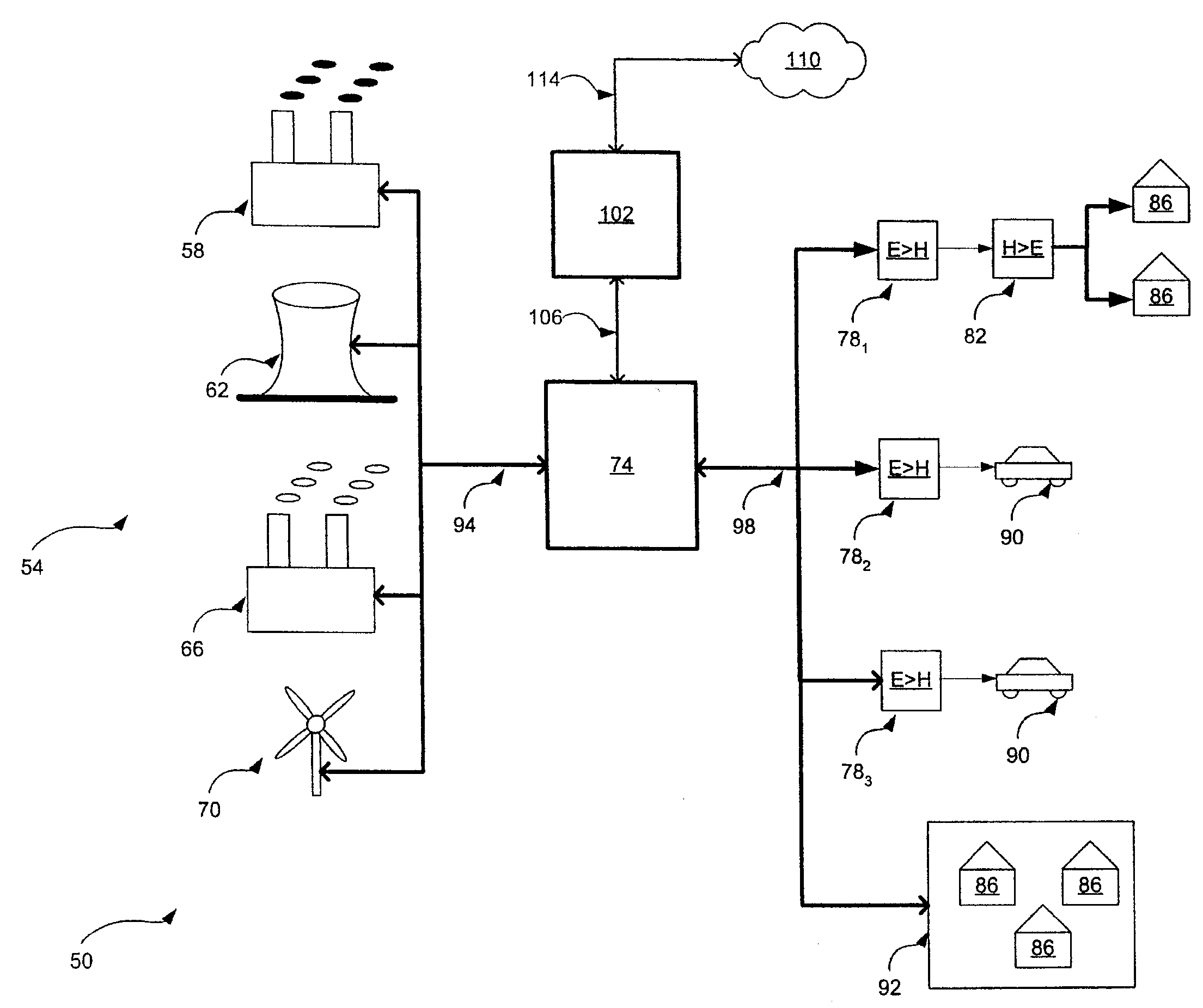
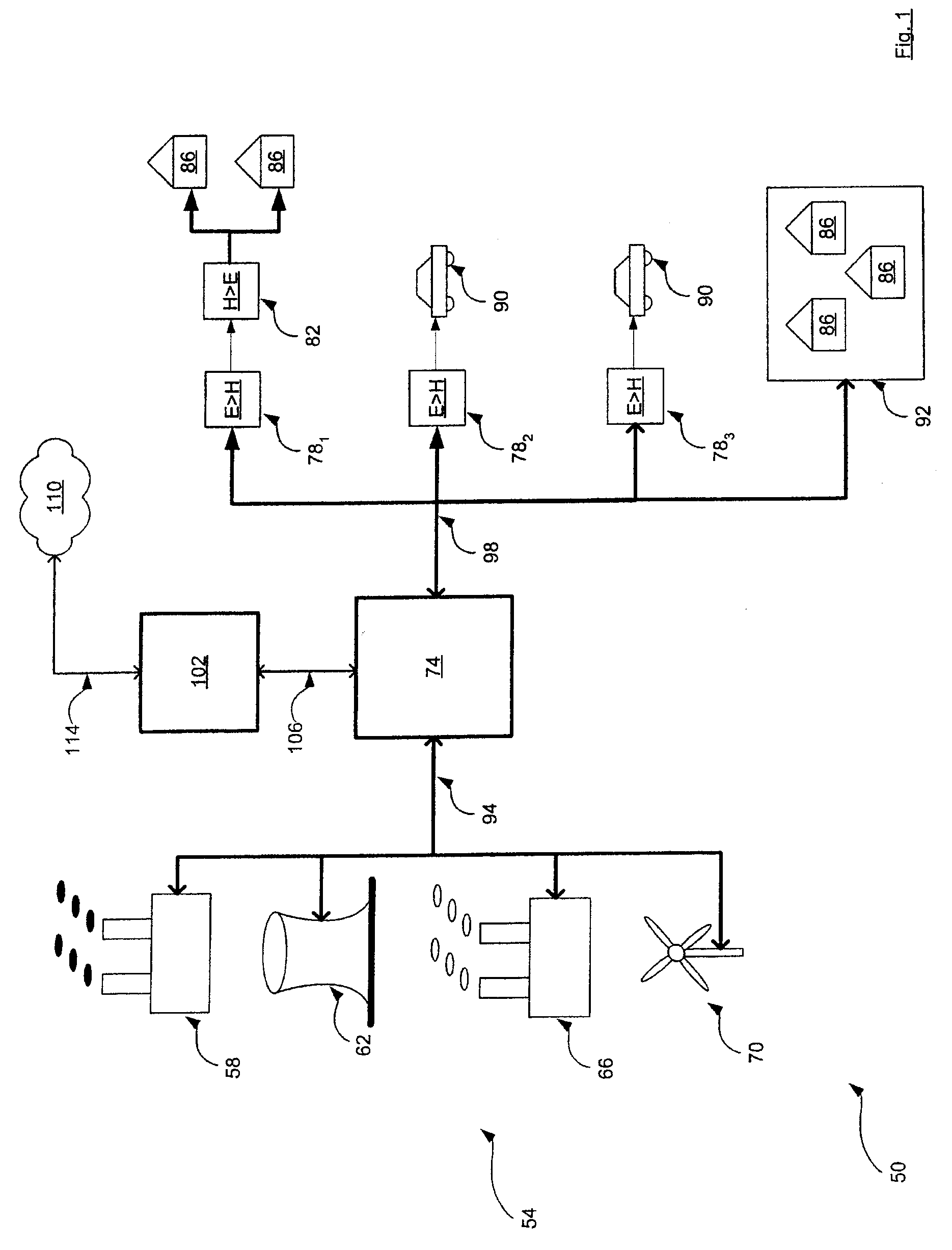
[0082] Referring now to FIG. 1, an energy network is indicated generally at 50. Network 50 includes a plurality of electrical generating stations 54. In a present embodiment, electrical generating stations include a coal power plant 58, a nuclear power plant 62, a natural gas power plant 66, and a wind-farm 70. As will be discussed in greater detail below, each electrical generating station 54 has a profile relating to the amount of energy it can generate, and another profile relating to the environmental pollutants associated with that energy generation.

[0083] Network 50 also includes a power grid 74, which is substantially the same as any conventional electrical power distribution grid, including transmission lines, power stations, transformers, etc. as is currently known or may become known.

[0084] Network 50 also includes a plurality of electrolysers 78, that are connected to grid 74, and which are operable to convert electricity from grid 74 into hydrogen, and store that hydro...


PUM

PropertyMeasurementUnit
energyaaaaaaaaaa
electricalaaaaaaaaaa
pressureaaaaaaaaaa

Abstract

An energy network is provided. An embodiment includes a network having a plurality of power stations and a plurality of loads interconnected by an electricity grid. The loads include electrolysers. The network also includes a controller that is connected to both the stations and the loads. The controller is operable to vary the available power from the power stations and / or adjust the demand from the electrolysers to provide a desired match of availability with demand and produce hydrogen as a transportation fuel with specific verifiable emission characteristics

Description

PRIORITY CLAIM [0001] The present application is a continuation application claiming priority from PCT Patent Application Number PCT / CA2004 / 001806, filed on Oct. 7, 2004, Canadian Patent Application Number 2,455,689 filed on Jan. 23, 2004 and U.S. Non-Provisional patent application Ser. No. 10 / 890,162 filed on Jul. 14, 2004, the contents of all of which are incorporated herein by reference.FIELD OF THE INVENTION [0002] The present invention is directed to the generation and distribution of energy and more particularly to energy networks. BACKGROUND OF THE INVENTION [0003] Hydrogen can be used as a chemical feed-stock and processing gas, or as an energy carrier for fueling vehicles or other energy applications. Hydrogen is most commonly produced from conversion of natural gas by steam methane reforming or by electrolysis of water. Comparing hydrogen as an energy carrier with hydrocarbon fuels, hydrogen is unique in dealing with emissions and most notably greenhouse gas emissions beca...

Claims


Application Information

Patent Timeline
Patent Type & Authority Applications(United States)
IPC IPC(8): H02J3/00C25B1/04F17D1/04F17D5/08H01M8/0612H01M8/0656H02J3/14H02J3/38
CPCF17D1/04F17D5/08H01M8/04089H01M8/04313H01M8/04694H01M8/04955H01M8/0656H01M8/184H02J3/14H02J3/38Y02E60/34Y02E60/528Y02P90/45Y02E60/50Y02E60/36H02J2310/58H02J2310/64H02J3/144Y04S50/10
Inventor FAIRLIE, MATTHEW
Owner STUART ENERGY SYST
Why Eureka
Try Eureka