Systems and methods for measuring uniformity in images

a technology of uniformity and image, applied in the field of systems and methods for measuring uniformity in images, can solve problems such as non-uniformity level errors, visual objectionable banding in halftone outputs, and errors typically arise in raster scan image output terminals (iots)

Active Publication Date: 2006-09-21
XEROX CORP
View PDF6 Cites 65 Cited by
  • Summary
  • Abstract
  • Description
  • Claims
  • Application Information

AI Technical Summary

Problems solved by technology

Even small non-uniformity level errors in raster scan IOTs give rise to visually objectionable banding in halftone outputs (e.g., image macro non-uniformity streak artifacts).
Such errors typically arise in raster scan image output terminals (IOTs) due to variations in ROS spot size across the field (which is constant in time (print to print)), donor-roll once-around, HSD wire hysteresis, laser diode variations, LED bar power variation, ROS scan line non-uniformity, photoreceptor belt sensitivity variations, and/or ROS velocity non-uniformity.
Although techniques have been proposed to eliminate such non-uniformity errors by making physical systems more uniform, it is too expensive to control or limit the error to an acceptable level, below which the error will not be detected by the unaided eye.
Fixes have been attempted in the marking process, but not enough latitude exists to fully solve the problem.
However, none of the solutions discusse

Method used


Image

  • Systems and methods for measuring uniformity in images
  • Systems and methods for measuring uniformity in images
  • Systems and methods for measuring uniformity in images

Examples


Embodiment Construction

[0033] While the method to process scanned images for uniformity will hereinafter be described in connection with exemplary embodiments, it will be understood that it is not intended to limit the embodiments. On the contrary, it is intended to cover all alternatives, modifications and equivalents as may be included within the spirit and scope of the embodiments as defined by the appended claims.

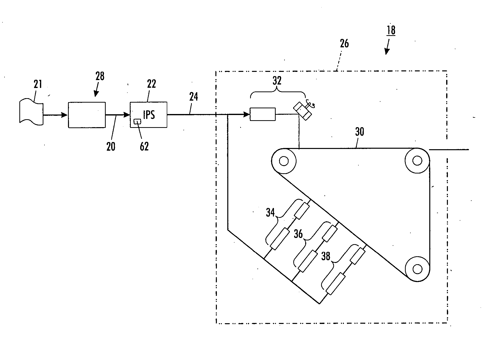
[0034] Turning now to FIG. 1, there is shown an embodiment of a digital imaging system 18 that incorporates the features of the exemplary embodiments. Image data 20 representing an image 21 to be printed is received by an image processing system (IPS) 22 that may incorporate what is known in the art as a digital front end (DFE). The IPS 22 processes the received image data 20 to produce print ready data 24 that is supplied to an output device 26 (e.g., a print engine). It is to be understood that the output device 26 may be a color xerographic printer. The IPS 22 may receive image data 20 fr...


PUM


Abstract

A method for measuring spatial uniformity in an image is provided and includes printing a test pattern from an image forming device having a plurality of strips and rows of fiducials proximal thereto. The method further provides for correcting of distortions in an image caused by printing and scanning artifacts and mapping from scanner coordinates to digital image coordinates. A gray level of each strip in the plurality of strips is determined as a function of digital image cross process coordinate. The method further provides for a profile of each strip to be filtered whereby the artifacts from a halftone screen are eliminated.

Description

CROSS REFERENCE TO RELATED APPLICATIONS [0001] The subject application is related to the following co-pending application: U.S. application Ser. No. 10 / 739,177, filed Dec. 19, 2003, by Howard Mizes, entitled “Systems and Methods for Compensating For Streaks in Images” (Attorney Docket No. A1268Q), which is herein incorporated by reference.BACKGROUND [0002] The exemplary embodiments relate to the art of digital imaging. It finds particular application in macro uniformity corrections for non-uniformities in a raster output scanning (ROS) printing system and will be described with particular reference thereto. It will be appreciated, however, that the disclosure is also amenable to other like applications. [0003] Macro non-uniformity levels have existed in raster scan image output terminals (IOTs) (e.g., xerographic printers) for some time and are a concern for most marking processes. Even small non-uniformity level errors in raster scan IOTs give rise to visually objectionable banding...

Claims


Application Information

Patent Timeline
IPC IPC(8): B41J3/00
CPCB41J29/393H04N1/506
Inventor MIZES, HOWARD
Owner XEROX CORP
Why Eureka
Try Eureka