Optical sheet and backlight unit having the same

a backlight unit and optical sheet technology, applied in the field of optical sheets, can solve the problems of narrow viewing angle, light loss, and inability to contribute to the brightness of the front of the lc panel, and achieve the effect of wide viewing angle and improved brightness

Active Publication Date: 2006-09-21
LG DISPLAY CO LTD
View PDF4 Cites 28 Cited by
  • Summary
  • Abstract
  • Description
  • Claims
  • Application Information

AI Technical Summary

Benefits of technology

[0021] An advantage of the present invention is to provide an optical sheet and a backlight unit having the same, capable of providing a wide viewing angle and improving brightness by providing a semicircular lens array sheet replacing a prism sheet and forming a diffuser film having a plurality of protrusions arranged in a direction perpendicular to the arrangement direction of the semicircular lens array sheet below the semicircular lens array sheet.
[0022] Additional features and advantages of the invention will be set forth in part in the description which follows and in part will become apparent to those having ordinary skill in the art upon examination of the following or may be learned from practice of the invention. The objectives and other advantages of the invention may be realized and attained by the structure particularly pointed out in the written description and claims hereof as well as the appended drawings.
[0023] To achieve these and other advantages and in accordance with the purpose of the present invention, as embodied and broadly described, there is provided an optical sheet including: a substrate; a lens array having a plurality of elongated lenses arranged on an upper surface of the substrate; and a diffuser film on a lower surface of the substrate and having a plurality of protrusions, each of the protrusions being arranged in a direction perpendicular to the direction of each of the lenses.
[0024] In another aspect of the present invention, there is provided a backlight unit including: a lamp disposed on a lateral side; a light guide plate disposed in the same plane as that of the lamp to change light from the lamp into a surface light source; and an optical sheet disposed on an upper surface of the light guide plate to compensate a viewing angle of the light, wherein the optical sheet includes: a substrate; a lens array having a plurality of elongated lenses arranged on an upper surface of the substrate; and a diffuser film on a lower surface of the substrate and having a plurality of protrusions, wherein each of the protrusions is arranged in a direction perpendicular to the direction of each of the lenses.
[0025] In a further another aspect of the present invention, there is provided a backlight unit including: a plurality of lamps arranged in the same plane; and an optical sheet disposed on the lamps to compensate a viewing angle of the light, wherein the optical sheet includes: a substrate; a lens array having a plurality of elongated lenses arranged on an upper surface of the substrate; and a diffuser film on a lower surface of the substrate and having a plurality of protrusions, wherein each of the protrusions is arranged in a direction perpendicular to the direction of each of the lenses.
[0026] It is to be understood that both the foregoing general description and the following detailed description of the present invention are exemplary and explanatory and are intended to provide further explanation of the invention as claimed.

Problems solved by technology

However, when the light incident to an inclined plane 24 of the protrusion 22 is not emitted due to a total internal reflection, such light is lost, and does not contribute to brightness at the front of the LC panel.
In that case, the front brightness may be improved but a viewing angle becomes narrow, that is not appropriate for flat display devices that require a wide viewing angle such as a television for home use.
In that case, the number of parts and manufacturing costs of the LCD increase.

Method used


Image

  • Optical sheet and backlight unit having the same
  • Optical sheet and backlight unit having the same
  • Optical sheet and backlight unit having the same

Examples


Embodiment Construction

[0036] Reference will now be made in detail to an embodiment of the present invention, examples of which are illustrated in the accompanying drawings.

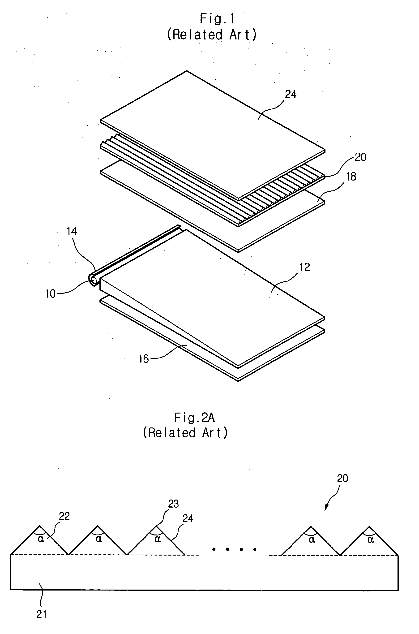
[0037] As described above, to overcome the problems of the related art prism sheet of a backlight unit of an LCD, a semicircular lens array sheet is used instead of the prism sheet.

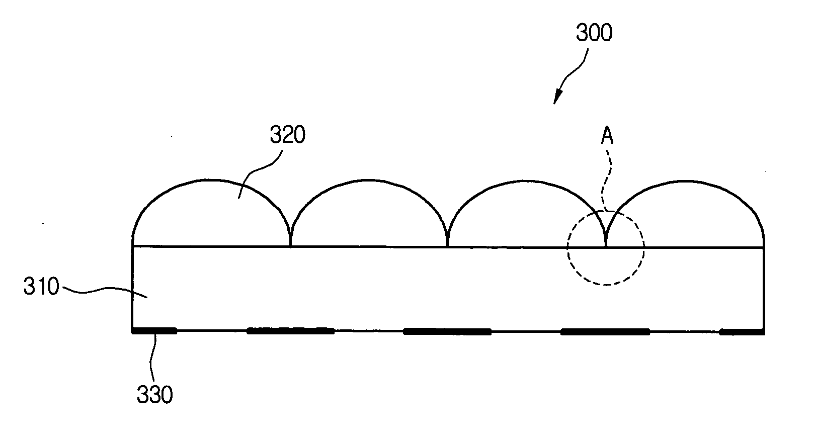
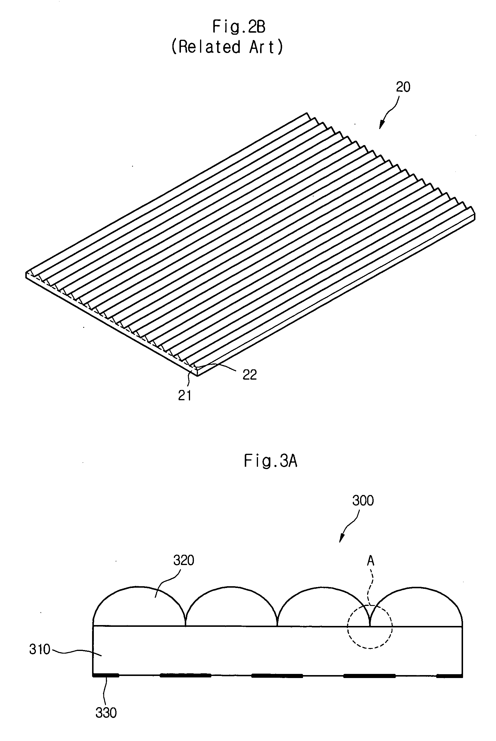
[0038]FIGS. 3A and 3B are a sectional view and a perspective view of a semicircular lens array sheet provided to a backlight unit of an LCD.

[0039] Referring to FIGS. 3A and 3B, the semicircular lens array sheet 300 includes: a substrate 310 to which light diffused by a light guide plate and / or a diffuser sheet is initially incident; a semicircular lens array 320 for allowing the diffused light to progress along a constant optical path; and a reflection pattern 330 formed on the lower portion of the substrate 310 that corresponds to a valley A to prevent light from being incident to the valley A (i.e., the region where the semicircular lenses contact each ...


PUM


Abstract

An optical sheet and a backlight unit having the same are provided. The optical sheet includes a substrate, a lens array, and a diffuser film. The lens array includes a plurality of lenses arranged on an upper surface of the substrate and the diffuser film disposed on a lower surface of the substrate and including a plurality of protrusions. Each of the protrusions is arranged in a direction perpendicular to the direction of each of the lenses, so that a viewing angle characteristic is improved and brightness is enhanced.

Description

[0001] This application claims the benefit of Korean Application No. 021655 / 2005, filed on Mar. 16, 2005, which is incorporated by reference for all purposes as if fully set forth herein. BACKGROUND OF THE INVENTION [0002] 1. Field of the Invention [0003] The present invention relates to an optical sheet, and more particularly, to an optical sheet and a backlight unit having the same. [0004] 2. Discussion of the Related Art [0005] Liquid crystal display devices (LCDs) display images by controlling pixels arranged in a matrix configuration to adjust the displacements of liquid crystal (LC) molecules and thus adjust light transmittance. Because the LCDs do not generate light by themselves, the LCDs receive light from an external light source, e.g., a backlight unit. [0006]FIG. 1 is a view of a backlight unit of the related art LCD. [0007] Referring to FIG. 1, the LCD includes: a lamp 10 disposed at a side of the LCD to generate light; a lamp housing 14 enclosing the lamp 10; a light g...

Claims


Application Information

Patent Timeline
Patent Type & Authority Applications(United States)
IPC IPC(8): F21V7/04
CPCG02B6/0046G02B6/0051A01K89/00A01K93/00
Inventor LEE, MANHOANLEE, SUNG-KEUNSEO, CHANGKI
Owner LG DISPLAY CO LTD
Why Eureka
Try Eureka