
Method and equipment for implementing synchronous switching of CLOS cross connection matrix

a cross-connection matrix and synchronization technology, applied in data switching networks, time-division multiplexing selection, digital transmission, etc., can solve the problems of increasing the design complexity of square matrix, affecting the operation of equipment, and only being feasible, so as to avoid the phenomenon of instantaneous disconnection

Inactive Publication Date: 2006-09-21
HUAWEI TECH CO LTD
View PDF6 Cites 22 Cited by
  • Summary
  • Abstract
  • Description
  • Claims
  • Application Information

AI Technical Summary

Benefits of technology

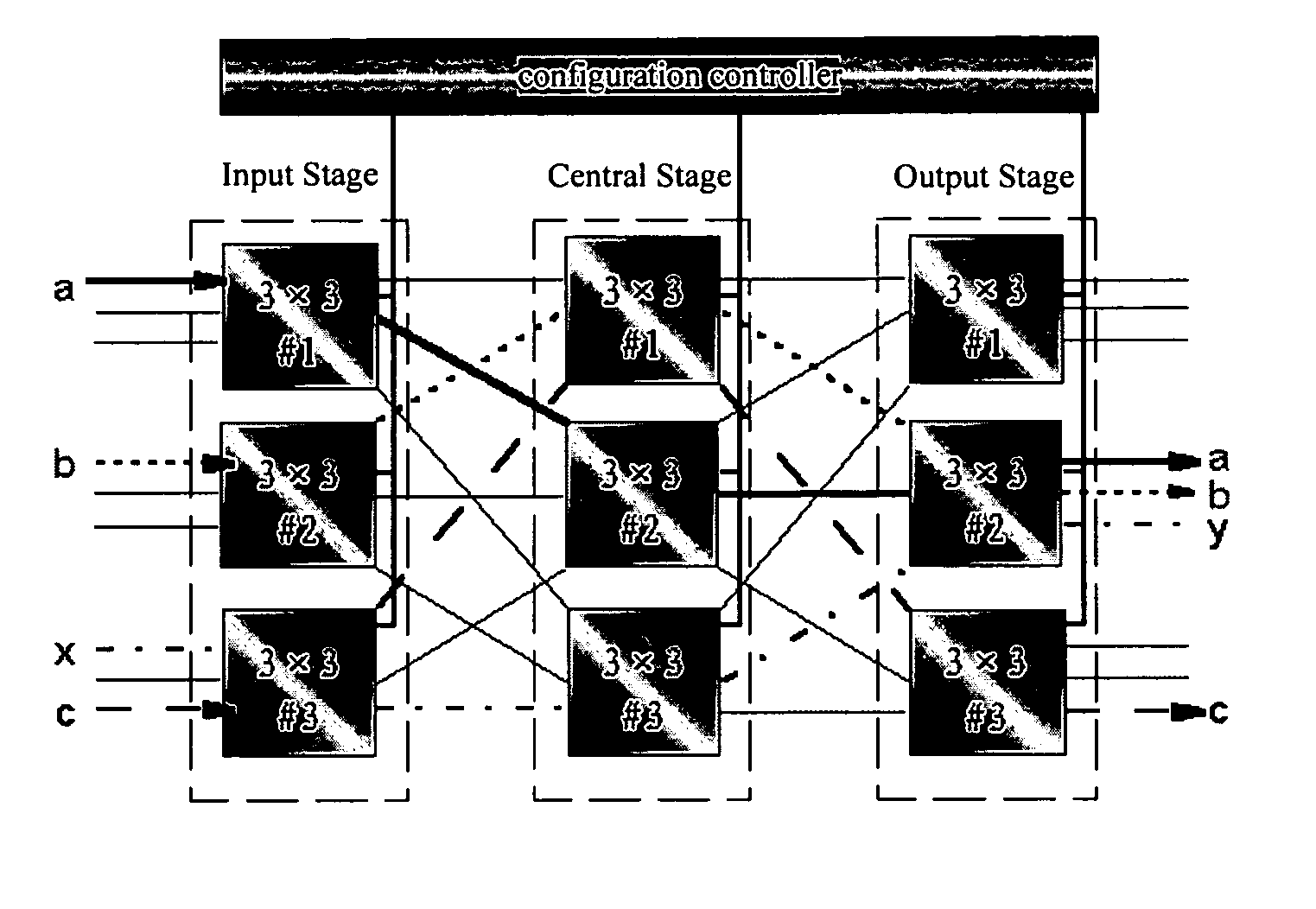
[0015] In view of the above, the present invention is to provide a method for implementing synchronous switching of a CLOS cross connection matrix, which guarantees synchronous switching of the input stage, the central stage and the output stage thereof and avoids the phenomenon of instantaneous disconnection.
[0016] The present invention is also to provide a digital cross connection equipment, which guarantees synchronous switching of the input stage, the central stage and the output stage of a CLOS cross connection matrix and avoids the phenomenon of instantaneous disconnection.
[0029] In Step d), if not all the ready signals from the cross nodes requiring synchronous switching are received during a predefined time span T0, the configuration controller may directly trigger a synchronous switching signal, i.e. sending a synchronous switching signal to the cross nodes that have returned the ready signal and completing synchronous switching; and resends to the cross nodes that have not returned a ready signal the CLOS cross connection matrix so that asynchronous switching can be implemented.

Problems solved by technology

By square matrix, cross connection can be implemented 100% without block, which, however, is only feasible when the cross capacity is relatively small since the scale of square matrix increases in a squaring exponential growth.
When a large cross capacity is needed, the design complexity of square matrix will increase significantly and the cost of equipment will be considerable.
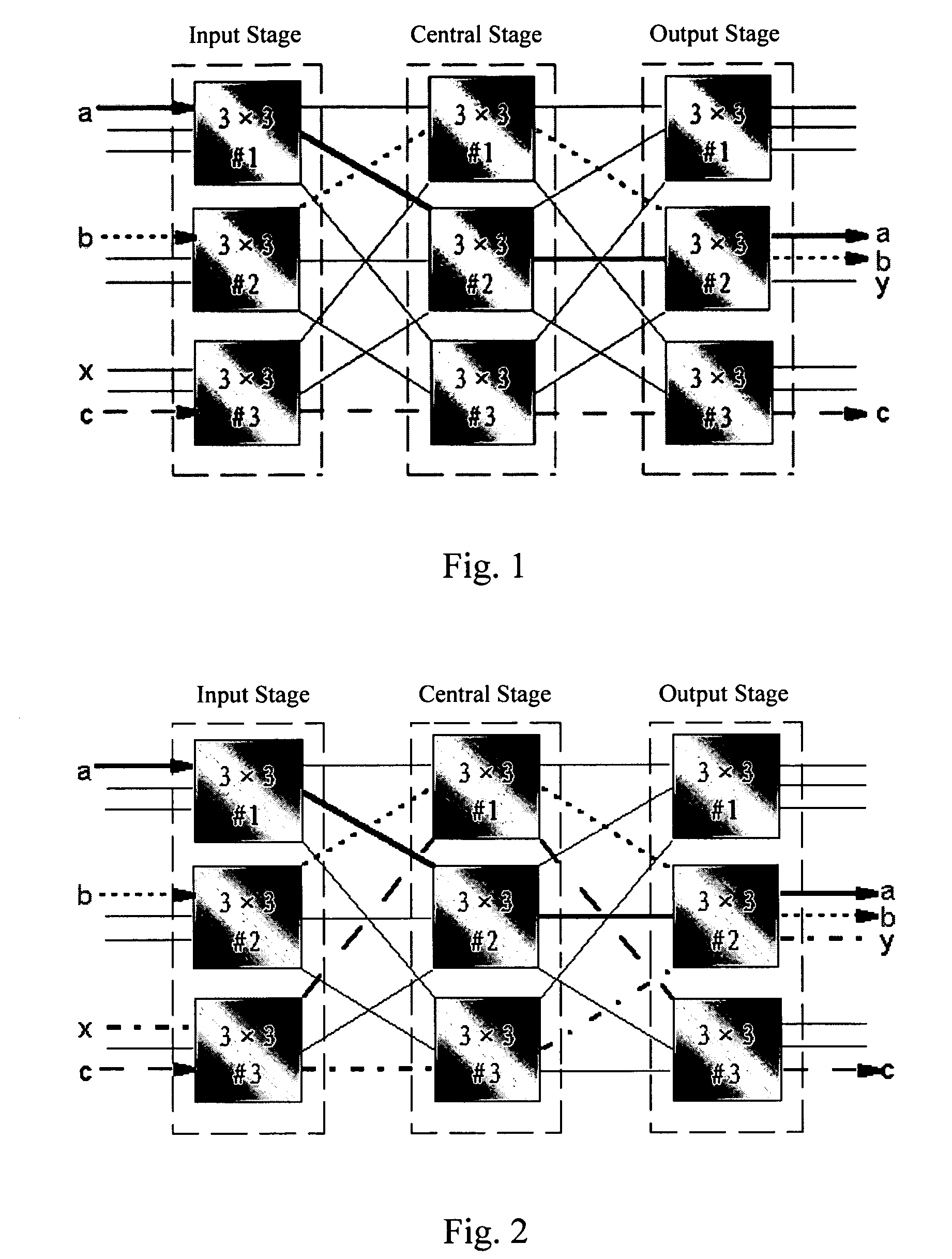
Though the introduction of CLOS cross connection matrix reduces design complexity, it also greatly reduces the match ratio of cross connections, which results in frequent cross connection adjusting and instantaneous disconnections of part of / all the original cross connections when cross connections are changed.
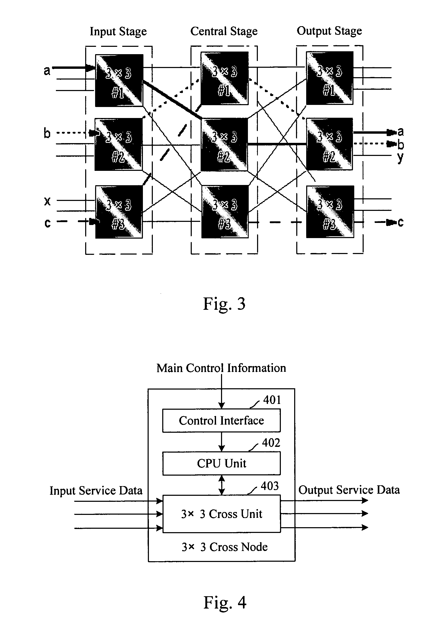
However, what must be considered is: when adjusting a cross connection (adjusting the connection of c->c in the present instance), if the input stage, the central stage and the output stage are not switched synchronously, instantaneous disconnection will inevitably happen to the original cross connections.
Although the in-band synchronous message mechanism provides a solution to synchronous configuration, there are some problems caused by the characteristics in the implementation of this message mechanism.
Since synchronous switching is implemented by inserting specific overhead bytes at a specific position, a set of synchronous switching protocols are needed and pure hardware logic needs to be added in each stage to implement the protocols, thus the cost is relatively high.
The in-band synchronous message mechanism is of poor applicability and can not meet the requirements of various occasions of application; for instance, the protocol applicable to 3-stage CLOS cross connection matrix is not applicable to 4-stage CLOS cross connection matrix, i.e. different protocols have to be developed based on different CLOS cross connection matrixes in order to implement the in-band synchronous message mechanism.

Method used


Image

  • Method and equipment for implementing synchronous switching of CLOS cross connection matrix
  • Method and equipment for implementing synchronous switching of CLOS cross connection matrix
  • Method and equipment for implementing synchronous switching of CLOS cross connection matrix

Examples


embodiment 1

[0057] The present embodiment is the embodiment of the first way mentioned above. FIG. 6 is a schematic diagram illustrating the structure of the configuration controller and the connection thereof with the input stage according to this exemplary embodiment of the present invention.

[0058] In the present embodiment, the main control board of the equipment is connected to a configuration controller 610 and cross nodes of each stage, respectively, wherein the main control board receives cross connection requests from the outside, submits the cross connection requests to the configuration controller 610 and sends control commands to the cross nodes to control and manage the cross nodes. In the present embodiment, both the information sent to the configuration controller 610 by the main control board and the information of the control and management commands sent to 3×3 cross nodes by the main control board are called main control information.

[0059] In FIG. 6, the configuration control...

embodiment 2

[0103] The present embodiment is the embodiment of the second implementing way mentioned above. FIG. 9 is a schematic diagram illustrating the structure of the configuration controller and the connection thereof with the input stage according to this second exemplary embodiment of the present invention.

[0104] In this embodiment, the configuration controller 910 comprises: a main-board CPU module 911 and a configuration interface 912. The main-board CPU model 911 receives cross connection requests from the outside, recalculates a CLOS cross connection matrix according to the cross connection requests, sends the new CLOS cross connection matrix to each 3×3 cross node in the input stage 900 through the configuration interface 912, and sends a synchronous switching signal to each 3×3 cross node simultaneously according to the ready signal returned by each 3×3 cross node. The main-board CPU module 911 of the present embodiment can also receive the switching completed signal returned by ...


PUM


Abstract

The present invention discloses a method for implementing synchronous switching of cross connections of a CLOS cross connection matrix, comprising: the configuration controller calculating a new CLOS cross connection matrix according to the cross request, sending this new CLOS cross connection matrix to the cross nodes requiring synchronous switching, and sending synchronous switching signal to all the cross nodes requiring synchronous switching after receiving the ready signals returned by all the cross nodes requiring synchronous switching, and the cross nodes performing the synchronous switching immediately after receiving the synchronous switching signal. The present invention also discloses a digital cross connection equipment containing a configuration controller for implementing synchronous switching of a CLOS cross connection matrix. With the present invention, synchronous switching of the input stage, the central stage and the output stage can be guaranteed without instantaneous disconnections.

Description

CROSS-REFERENCE TO RELATED APPLICATIONS [0001] This application is a continuation-in-part of PCT Application No. PCT / CN2004 / 001102, filed Sep. 27, 2004, pending, which designates the U.S., which is hereby incorporated herein by reference in its entirety, and which claims priority from Chinese Application No. 03126414.X, filed Sep. 27, 2003.FIELD OF THE INVENTION [0002] The present invention relates to a method for implementing synchronous switching of a cross connection matrix and equipment thereof, and more particularly to a method for implementing synchronous switching of a CLOS cross connection matrix and equipment thereof. BACKGROUND OF THE INVENTION [0003] In a Synchronous Digital Hierarchy / Synchronous Optical Network (SDH / SONET), a cross connection matrix is the core of synchronous digital cross connection equipment (hereinafter referred to as cross connection equipment). Typical cross connection matrixes include square matrix and CLOS cross connection matrix matrix. [0004] By...

Claims


Application Information

Patent Timeline
Patent Type & Authority Applications(United States)
IPC IPC(8): H04L12/56H04L12/50H04Q11/00H04L12/28H04L7/00H04Q3/00H04Q3/52H04Q3/545H04Q3/68H04Q11/06
CPCH04Q3/68H04Q2213/1302H04Q2213/1304H04Q2213/13076
Inventor LI, JUNANXIA, LEIZHANG, HONGXING
Owner HUAWEI TECH CO LTD
Learn More