Method and device for laser micromachining

Active Publication Date: 2016-09-22
CENT NAT DE LA RECHERCHE SCI
View PDF5 Cites 17 Cited by
  • Summary
  • Abstract
  • Description
  • Claims
  • Application Information

AI Technical Summary

Benefits of technology

[0036]the spatial conditioning of said first pulse allowing, after focusing in said sample, a non-diffracting beam focused according to a focusing cylinder to be formed, the light intensity of

Problems solved by technology

Ebeam technology, which requires a high vacuum, is adapted to holes with diameters of less than 100 nm and is slow to machine.
Photolithographic technology requires the

Method used


Image

  • Method and device for laser micromachining
  • Method and device for laser micromachining
  • Method and device for laser micromachining

Examples


Embodiment Construction

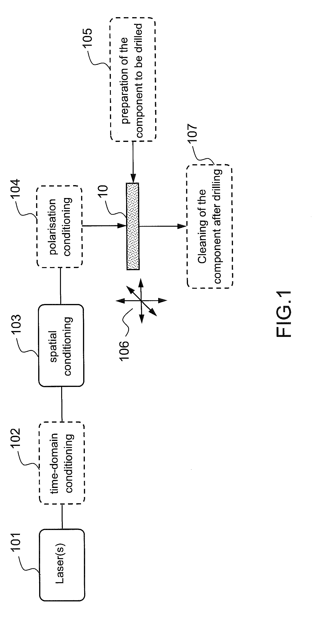
[0062]FIG. 1 illustrates, with a diagram, a first example of a micromachining method according to the present description, applied to drilling into a sample.

[0063]According to this example, the micromachining method comprises an emission 101 of a beam by a pulsed laser source, and the focusing of the beam onto a sample 10 to be drilled, after a time-domain conditioning step 102 (optional), a spatial conditioning step 103 and a polarization conditioning step 104 (optional) which will be described in more detail hereinbelow. The scanning of the beam and the translation / rotation (symbolized by the arrows 106) of the sample can allow a relative movement between the beam and the sample in order to carry out several drillings sequentially on the same sample. According to one variant, as will be described in more detail hereinafter, the component to be drilled may be prepared prior to the drilling operation (step 105) and a step for cleaning the component after drilling (step 107) may also...


PUM

PropertyMeasurementUnit
Timeaaaaaaaaaa
Poweraaaaaaaaaa
Chemical propertiesaaaaaaaaaa

Abstract

The invention, according to an aspect thereof, relates to a device (60) for laser micromachining a sample made of a given material, which includes a focusing module enabling a nondiffracting beam to be generated from a given incident beam, said nondiffracting beam being focused along a focusing cylinder that is oriented generally along the optical axis of the focusing module, means (601) for transmitting at least one first light pulse (11) suitable for generating, after said focusing module focuses in the sample, a plasma of free charges by multiphotonic absorption in a volume of the sample located on the side surface of said focusing cylinder

Description

PRIOR ART[0001]1. Technical Field of the Invention[0002]The present invention relates to a method and a device for high-speed laser micromachining, adapted notably for the micro-drilling of materials for microelectronics.[0003]2. Prior Art[0004]Various techniques are known for drilling channels or “vias” in or through semiconductor wafers for micro- and nanoelectronics and for photovoltaics.[0005]These drilling techniques comprise for example the focusing of beams of ions (process referred to as “ebeam”) or photolithography followed by deep reactive ion etching (or DRIE). Ebeam technology, which requires a high vacuum, is adapted to holes with diameters of less than 100 nm and is slow to machine. Photolithographic technology requires the prior formation of a mask; it is therefore not very flexible and costly.[0006]In the field of the micro- / nano-structuring of dielectric materials (for example glass), the inventors have shown that the use of a femtosecond laser beam with a “non-diff...

Claims


Application Information

Patent Timeline
IPC IPC(8): B23K26/0622B23K26/388B23K26/40B23K26/073
CPCB23K26/0622B23K26/0734B23K2203/52B23K26/40B23K2201/40B23K26/388B23K26/0624B23K26/389B23K2103/50B23K2101/40B23K2103/52
Inventor COURVOISIER, FRANCOISLACOURT, PIERRE-AMBROISECOUAIRON, ARNAUD
Owner CENT NAT DE LA RECHERCHE SCI
Why Eureka
Try Eureka