Autostereoscopic imaging device and system comprising it

a technology of autostereoscopic imaging and imaging system, which is applied in the field of autostereoscopic imaging device and, can solve the problems of requiring precise positioning, reducing the dimensions of the lens array, and implementing much more complicated or even impossible problems

Inactive Publication Date: 2003-06-03
ALIOSCOPY
View PDF7 Cites 18 Cited by
  • Summary
  • Abstract
  • Description
  • Claims
  • Application Information

AI Technical Summary

Problems solved by technology

Unfortunately, the required accuracy of positioning is proportional to the number of lenticles.
In addition, video applications that require miniature cameras, e

Method used


Image

  • Autostereoscopic imaging device and system comprising it
  • Autostereoscopic imaging device and system comprising it
  • Autostereoscopic imaging device and system comprising it

Examples


second embodiment

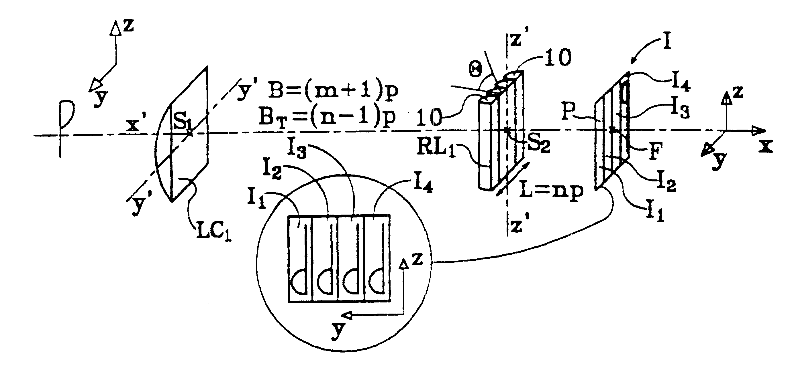
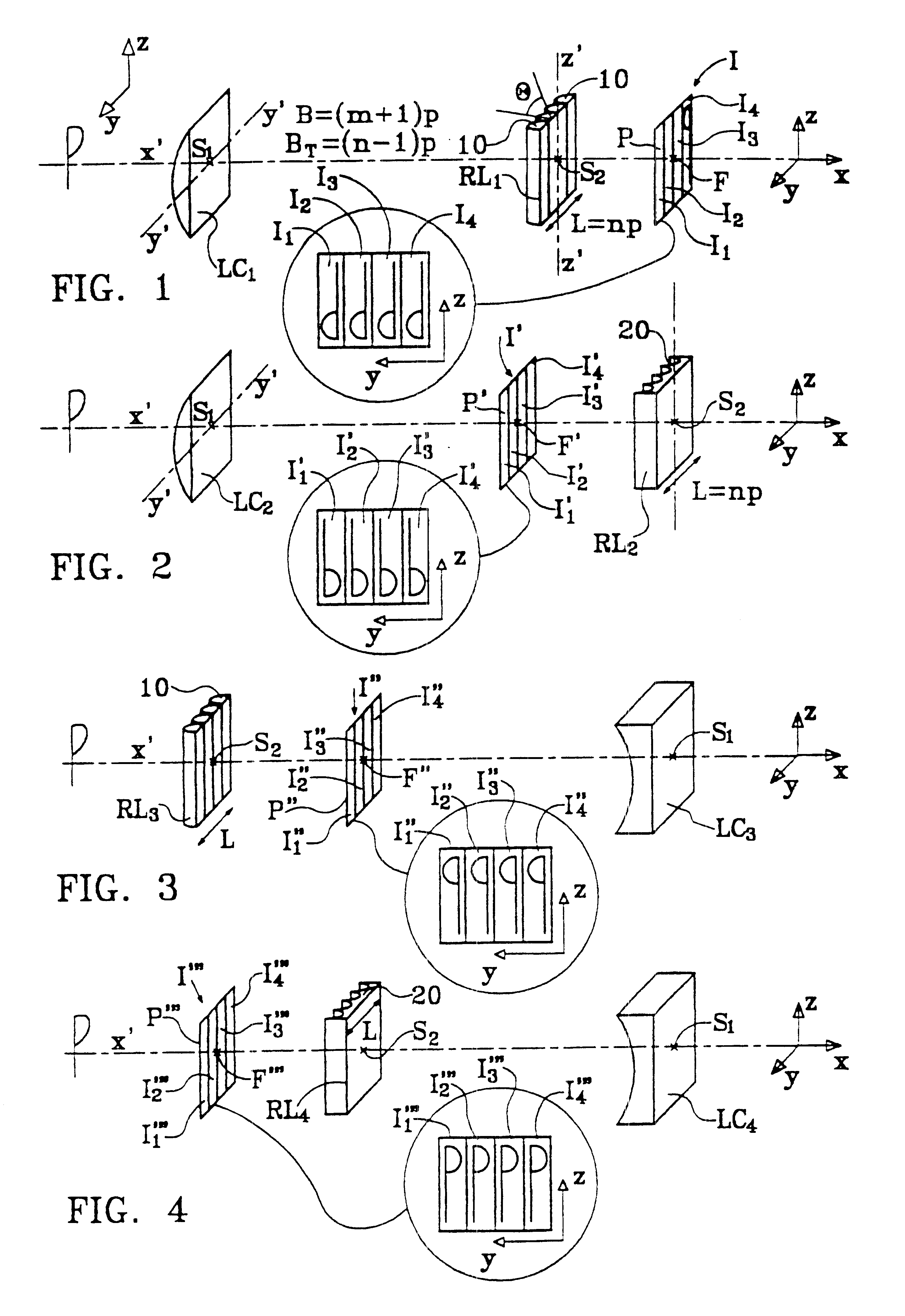
the invention as shown in FIG. 2 implements a converging cylindrical lens LC.sub.2 of horizontal axis perpendicular to the axis x'x, and a diverging lens array RL.sub.2 having n contiguous vertical-axis concave cylindrical lenticles 20. The lens LC.sub.2 and the array RL.sub.2 have a common focal plane P' which is situated between the cylindrical lens LC.sub.2 and the lens array RL.sub.2. The plane P' intersects the optical axis x'x at the focus F' and the elementary flat images of anamorphic format I'.sub.1, I'.sub.3, I'.sub.3 and I'.sub.4 are images in which the horizontal component is virtual and the real component is real.

To obtain an anamorphosis ratio that is substantially equal to n between the horizontal and vertical components of the elementary images, the ratio between the focal lengths of the cylindrical lens LC.sub.2 and of the elementary lenticles of the lens array RL.sub.2 is selected as in the preceding case to be substantially equal to -n, i.e. S.sub.1 F'=-nS.sub.2 F...

example i

The following values are selected: ##EQU6##

When the anamorphosis ratio C is exactly compensated for an object situated at 3 meters (m) from the cylindrical lens LC.sub.1, the ratio C is equal to 3.465 for an object situated at infinity, using above formula (4), i.e. .DELTA.C / C=13.3% and k=0.866.

For an object situated at 2 m, then C=4.55, i.e. .DELTA.C / C=13.8%.

For an anamorphosis coefficient that is exactly compensated at 3 m (C=4), the coefficient .DELTA.C / C lies in the range .+-.13% approx. from 2 m to infinity, which is entirely compatible with good quality picture-taking. Such deformation is progressive and it difficult for the observer to perceive. It can be compensated as a function of focusing distance, as indicated below.

It should be observed that when performing projection or back-projection, the projection coefficient k can be involved and it is thus the product of the coefficients k used when taking the picture and / or when projecting (or back-projecting it) that needs to b...

example ii

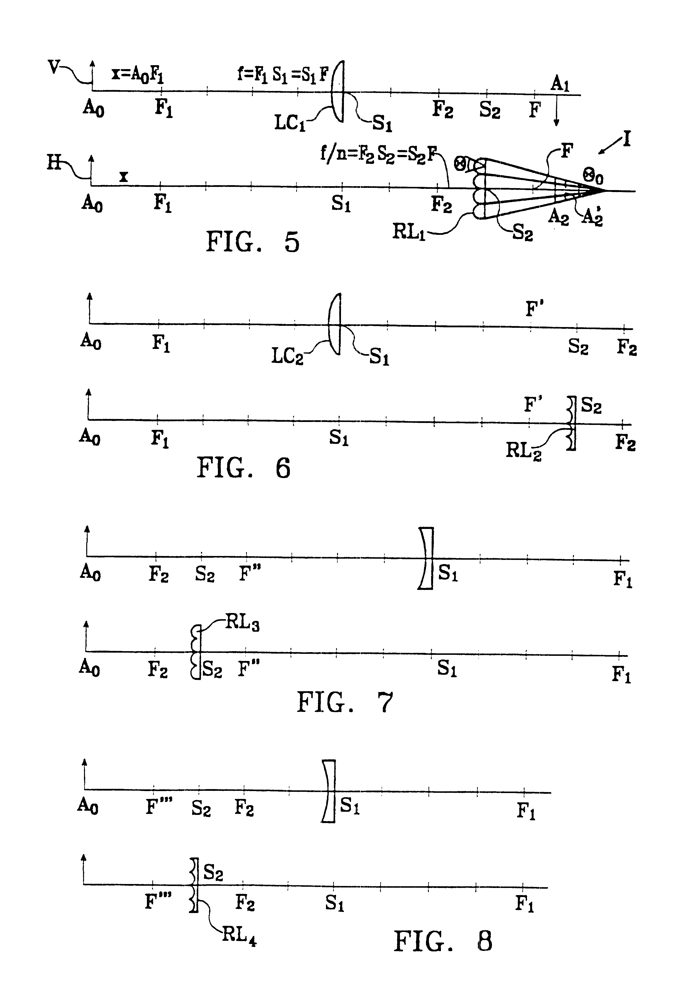
Converging Cylindrical Lens & Converging Lens Array (FIGS. 1 and 5), with f.sub.1 =0.1 m.

To obtain an anamorphosis coefficient C=4 with focusing at 4 m, calculation shows that the lenses of the converging lens array must have a focal length f.sub.2 =0.2598 m, i.e. n*=.vertline.f.sub.1 / f.sub.2.vertline.=3.85, i.e. k=n* / N=0.96.


PUM


Abstract

A device for forming an autostereoscopic image having n viewpoints, the device including a lens array (RL1) comprising cylindrical lens (10) having longitudinal axes parallel to a direction (zz') perpendicular to an optical axis (x'x) of the device. The device includes a cylindrical optical assembly whose longitudinal axis is perpendicular to zz' and to xx'. The lens array (RL1) comprises n cylindrical lens (10). The lens array (RL1) and the cylindrical optical assembly (LC1) share a common focusing plane (P) corresponding to a focusing distance DELTA. The absolute value of the ratio between the focal length of the cylindrical optical assembly and that of the lens array is substantially equal to n. Also provided is projection device implementing said image-forming device, and a projector projecting n flat elementary images, and a screen fitted with at least a projection array.

Description

FIELD AND BACKGROUND OF THE INVENTIONThe present invention relates to an autostereoscopic image-forming device comprising n viewpoints (or elementary images), said device including a lens array comprising elementary cylindrical lenses referred to as cylindrical "lenticles", placed side by side parallel to a first direction.It is known that such devices have been implemented to constitute autostereoscopic cameras, specifically the autostereoscopic picture-taking devices described in the Applicant's following patents: U.S. Pat. No. 5,099,320, and French patents FR-2 705 007 and 2 704 951.Those picture-taking devices implement a lens array having a large number of cylindrical lenticles placed side by side, and in practice, the video image is obtained in interleaved manner in the form of columns of pixels, the first elementary image being constituted by the pixels of the first column of pixels together with the pixels in the other columns offset therefrom modulo n, the second elementary...

Claims


Application Information

Patent Timeline
IPC IPC(8): G03B35/24G03B35/18G02B27/22H04N13/00G02B30/27H04N13/04
CPCG02B27/2214H04N13/0404H04N13/0228G03B35/24H04N13/305H04N13/229G02B30/27
Inventor ALLIO, PIERRE
Owner ALIOSCOPY
Why Eureka
Try Eureka