
Image encoding/decoding method and apparatus therefor

a technology of encoding/decoding and image, applied in the field of image encoding/decoding method for encoding/decoding, can solve the problems of inability to finely control the transformation coefficient in the small pixel block in the macroblock, and the inability to predict the prediction method, so as to achieve the prediction method and control the transformation coefficient according to the shape of the macroblock

Inactive Publication Date: 2006-09-21
KK TOSHIBA
View PDF4 Cites 100 Cited by
  • Summary
  • Abstract
  • Description
  • Claims
  • Application Information

AI Technical Summary

Benefits of technology

[0019] The object of the present invention is to provide a video encoding method for encoding an image by quantizing a predictive error signal in units of a block smaller than a macroblock referring to a quantization code table.

Problems solved by technology

Accordingly, there is a problem that transformation coefficients in a small pixel block in the macroblock cannot be finely controlled.
Further, when a quantization parameter is determined and dequantized for every macroblock by a method prescribed in the H.264 High profile, using a given quantization matrix, there is a problem that it is impossible to control transformation coefficients according to a predictive block shape in the macroblock and a prediction method.

Method used


Image

  • Image encoding/decoding method and apparatus therefor
  • Image encoding/decoding method and apparatus therefor
  • Image encoding/decoding method and apparatus therefor

Examples


first embodiment

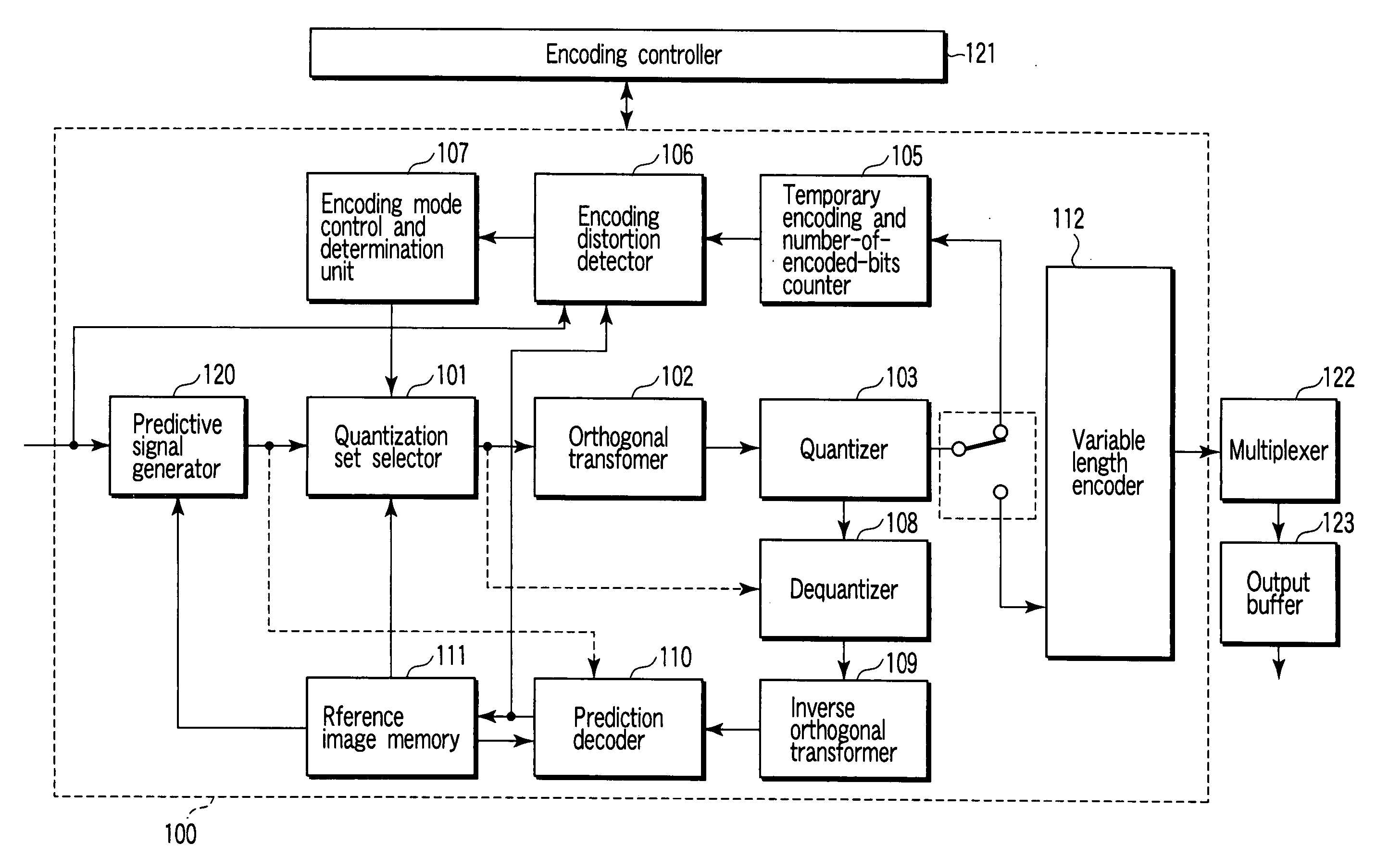
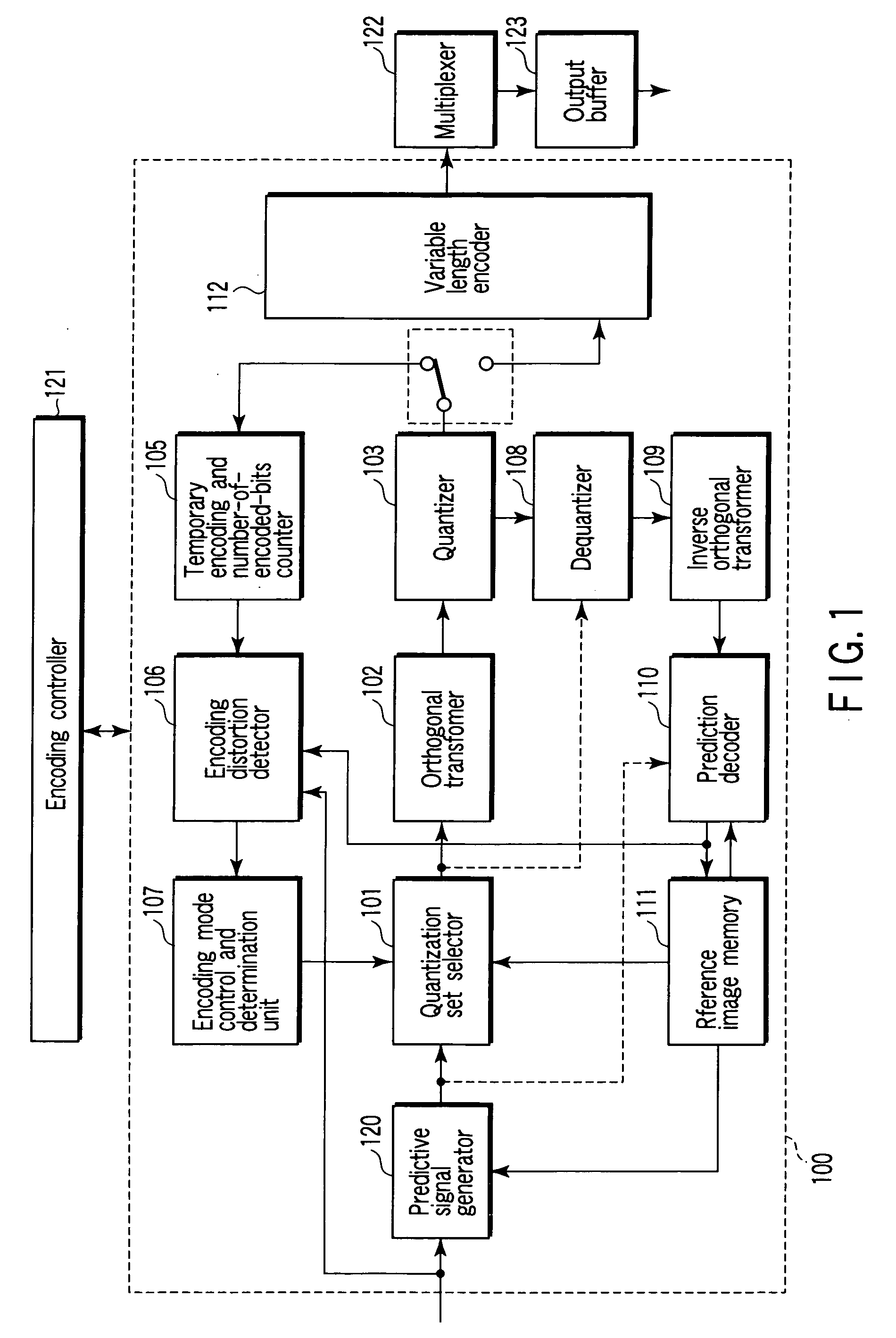
[0037]FIG. 1 is a block diagram of a video encoding apparatus related to the present invention. In this embodiment, a video image is encoded by quantizing a predictive error signal referring to a quantization code table in units of a block smaller than a macroblock.

[0038] According to FIG. 1, an input image signal, that is, a video signal is divided into macroblocks or macroblock pairs and input to a video encoding apparatus 100. In the video encoding apparatus 100, a plurality of prediction modes different in block size or predictive signal generation method from each other are prepared as an intra prediction mode and an inter prediction mode. The predictive signal generator 120 generates a predictive image in all modes selectable by a macroblock of a reference image stored temporarily in a reference image memory 111. Further, the predictive signal generator 120 generates a predictive error signal obtained by subtracting the predictive signal from the input image signal.

[0039] If ...

second embodiment

[0098] A video encoding method will be described.

[0099] In this embodiment, a step for selecting a corresponding quantization matrix corresponding for every pixel block is added to the first embodiment. In other words, this embodiment includes switching selectively a plurality of quantization matrices as well as determining an index representing a quantization parameter of a quantization code table. The configuration of a video encoding apparatus of the embodiment is similar to FIG. 1. In the second embodiment, like reference numerals are used to designate like structural elements corresponding to those like in the first embodiment and any further explanation is omitted for brevity's sake.

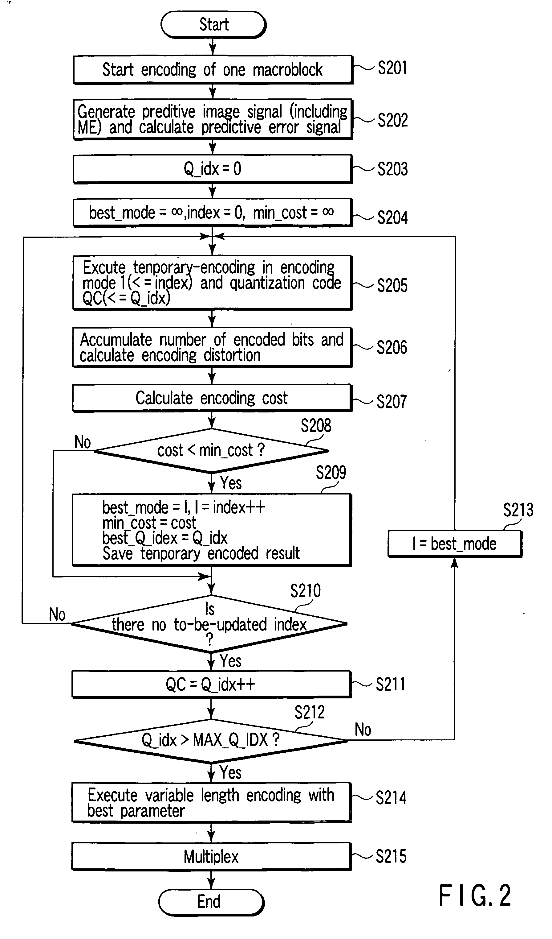
[0100]FIG. 11 shows a process flow of video encoding of this embodiment. Steps S1001 and S1002 are equal with steps S201 and S202 of FIG. 2, respectively. The encoding controller 121 initializes an index WM_idx indicating a table number of a quantization matrix to 0 (step S1003). Further, each va...


PUM


Abstract

An image encoding method includes generating a predictive signal and encoding mode information according to each encoding mode from a macroblock signal corresponding to each macroblock, selecting a quantization code table corresponding to each macroblock, generating a predictive error signal for each encoding mode based on the macroblock signal and the predictive signal, subjecting the predictive error signal to orthogonal transformation, quantizing the orthogonal-transformed predictive error signal while changing a quantization parameter for every plural sub-pixel-blocks, using the quantization code table corresponding to the macroblock, encoding quantization transformation coefficient, calculating an encoding cost, selecting one encoding mode based on the encoding cost, selecting one quantization code table based on the encoding cost, and encoding information of an index indicating the selected quantization code table for every frame of the input image signal or every region of the frame.

Description

CROSS-REFERENCE TO RELATED APPLICATIONS [0001] This application is based upon and claims the benefit of priority from prior Japanese Patent Application No. 2005-075935, filed Mar. 16, 2005, the entire contents of which are incorporated herein by reference. BACKGROUND OF THE INVENTION [0002] 1. Field of the Invention [0003] The present invention relates to an image encoding / decoding method for encoding / decoding a video or still image and an apparatus therefor. [0004] 2. Description of the Related Art [0005] In recent years, a video encoding method that the encoding efficiency is improved more largely than before is recommended for ITU-TRec.H.264 and ISO / IEC14496-10 in conjunction with ITU-T and ISO / IEC. A conventional encoding system such as ISO / IECMPEG-1,2,4, ITU-TH.261, H.263 performs compression with two-dimensional discrete cosine transformation (DCT) of a 8*8 block. In contrast, since an encoding system of H.264 uses two-dimensional integer orthogonal transformation of a 4*4 blo...

Claims


Application Information

Patent Timeline
IPC IPC(8): H04N11/04H04N7/12H04B1/66H04N11/02H04N19/50H03M7/30H04N19/00H04N19/126H04N19/136H04N19/14H04N19/146H04N19/196H04N19/503H04N19/513H04N19/61H04N19/625H04N19/91
CPCH04N19/176H04N19/70H04N19/147H04N19/192H04N19/61H04N19/126H04N19/19H04N19/15
Inventor TANIZAWA, AKIYUKICHUJO, TAKESHI
Owner KK TOSHIBA
Learn More