
Fixing device and image forming apparatus

Inactive Publication Date: 2006-09-21
FUJIFILM BUSINESS INNOVATION CORP
View PDF8 Cites 22 Cited by
  • Summary
  • Abstract
  • Description
  • Claims
  • Application Information

AI Technical Summary

Benefits of technology

[0014] An aspect of the present invention is a fixing device that fixes toner images carried on a recording material. The device includes a rotary member, a belt member that is brought into contact with the rotary member, wherein a nip part through which the recording material passes is formed between the belt member and the rotary mem

Problems solved by technology

Therefore, there is a problem in the picture quality such as fixing spot or paper wrinkle.
On the other hand, the method of increasing the diameter of the roller is also problematic in that the apparatus becomes bulky, and a warm-up time taken to raise a temperature of the roller from a room temperature to an available fixing temperature becomes long.
In particular, in the fixing device of belt nip mode, heat transferred from the fixing roller is difficult to emit because heat capacity of the endless belt pressed against the fixing roller is low.
As a result, there is a problem in that strain of a wave shape or wrinkles in the rotation direction is easily generated in the endless belt.
Furthermore, if strain of a wave shape or wrinkles is generated in the endless belt, there are problems in that fixity is degraded and the picture quality is lowered since adhesiveness between the fixing roller and the recording paper becomes low.
There is also a problem in that the picture quality is significantly degraded in a solid image such as, especially, a photo image because lowering in a brilliance of a toner image results in a so-called glazing spot.

Method used


Image

  • Fixing device and image forming apparatus
  • Fixing device and image forming apparatus
  • Fixing device and image forming apparatus

Examples


embodiment 1

[0026] Embodiment 1

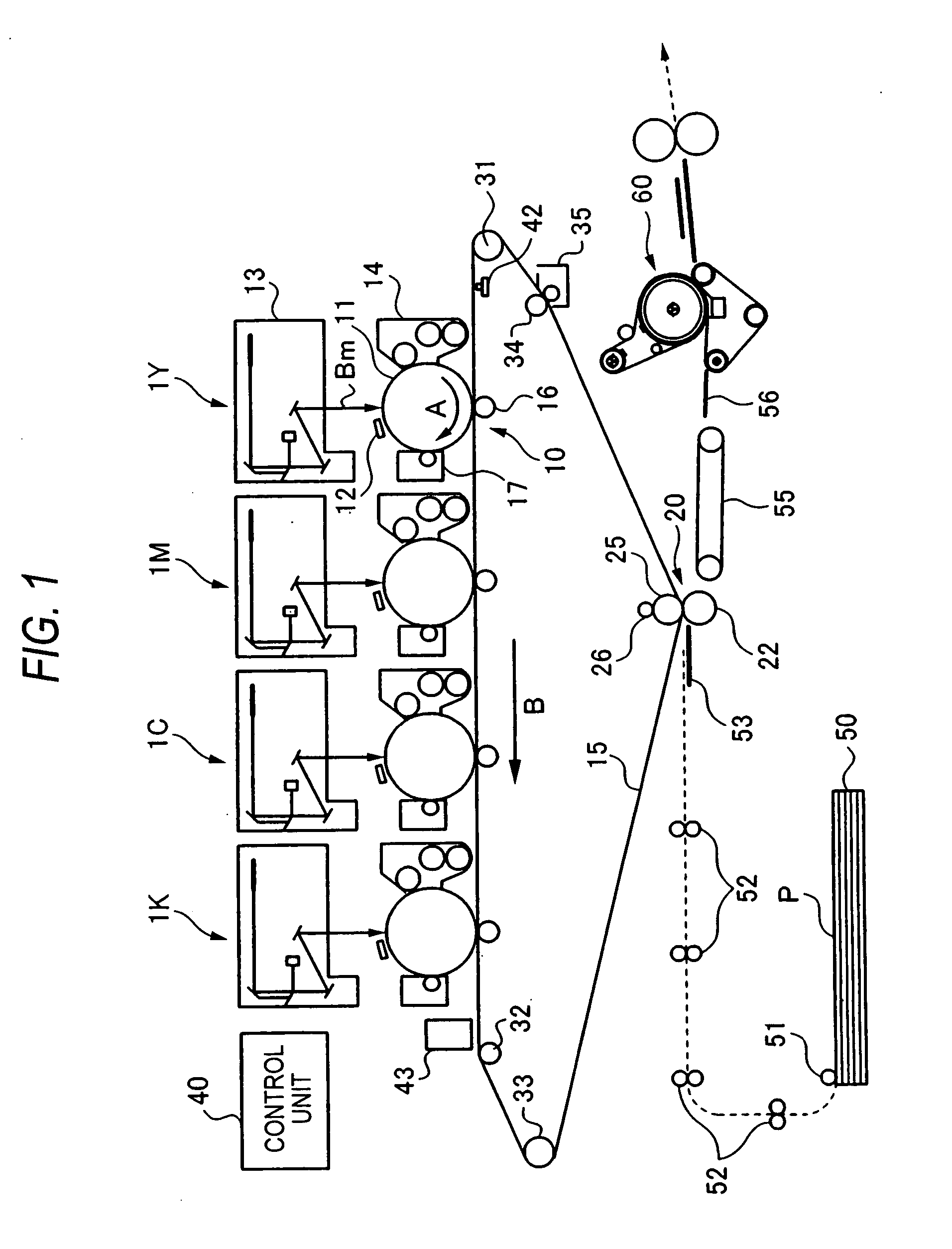
[0027]FIG. 1 is a schematic construction showing an image forming apparatus according to the present embodiment. The image forming apparatus shown in FIG. 1 is an image forming apparatus of intermediate transfer mode, which is generally referred to as “tandem type”. The image forming apparatus includes a plurality of image forming units 1Y, 1M, 1C and 1K on which color component toner images are respectively formed in electrophotographic mode, a primary transfer unit 10 that sequentially transfers (a primary transfer) the color component toner images respectively formed by the image forming units 1Y, 1M, 1C and 1K to an intermediate transfer belt 15, a secondary transfer unit 20 that batch-transfers (a secondary transfer) overlapping toner images transferred on the intermediate transfer belt 15 to paper P being a recording material (recording paper), and a fixing device 60 that fixes the images secondarily transferred on the paper P. The apparatus further includes...

embodiment 2

[0119] Embodiment 2

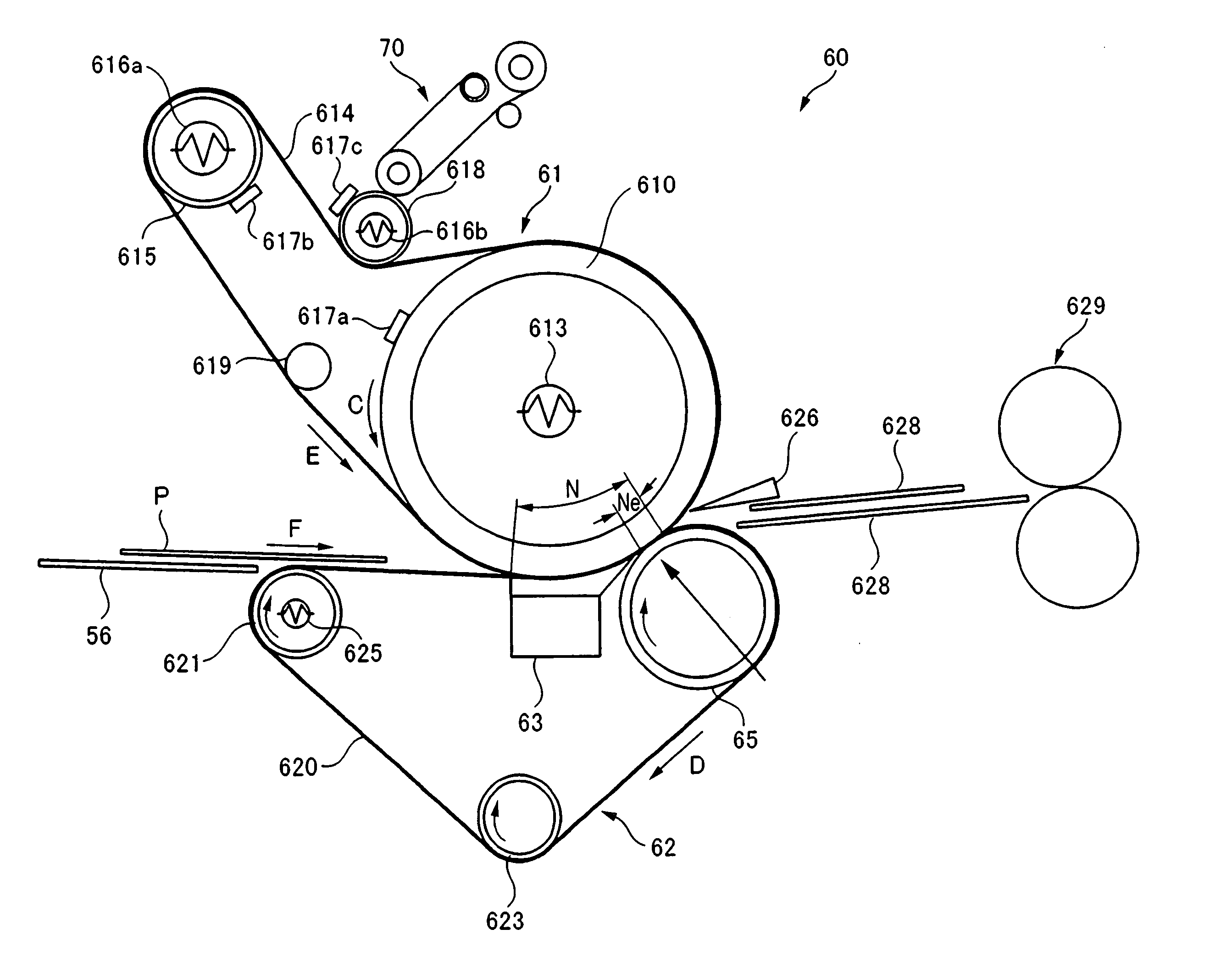
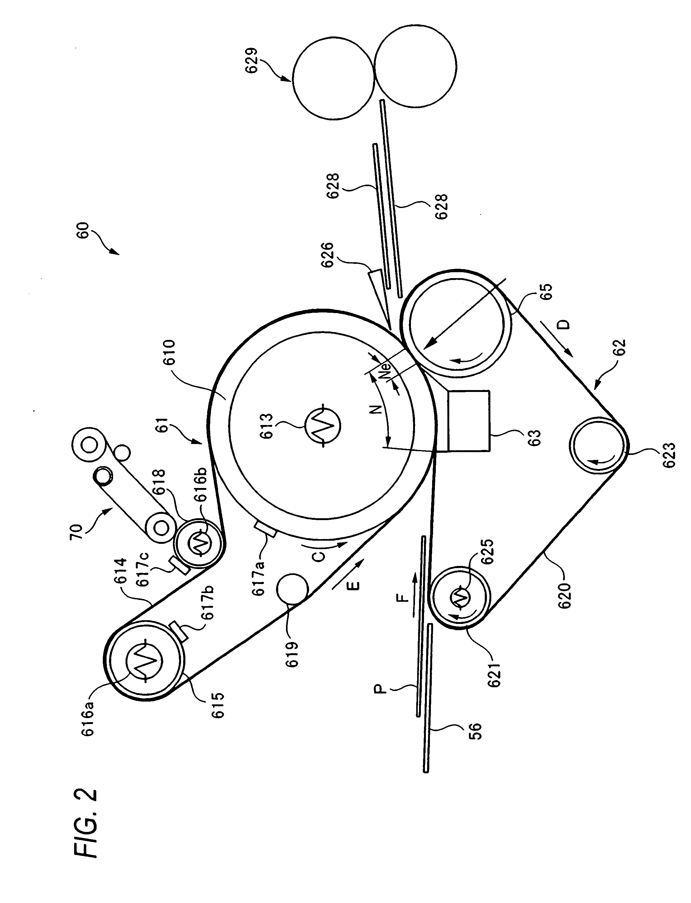
[0120] Embodiment 1 relates to the image forming apparatus. The construction of the image forming apparatus in which the fixing device 60 is mounted using the fixing belt module 61, wherein the fixing belt 614 of an endless shape is stretched by means of the stretching roller 615 and the stretching roller 618, the fixing roller 610 as the assistant heating members, as the heating member used in the fixing device 60, has been described. In Embodiment 2, the construction of a fixing device 90 mounted in the image forming apparatus shown in FIG. 1, wherein only the fixing roller 610 is disposed as a heating member used in the fixing device 60 will be described. In addition, the same reference numerals are used to identify the same parts as those of Embodiment 1. Detailed description thereof will be thus omitted.

[0121]FIG. 9 is a lateral sectional view showing the construction of the fixing device 90 according to Embodiment 2. The fixing device 90 of the present embo...


PUM


Abstract

A fixing device that fixes toner images carried on a recording material, including: a rotary member; a belt member that is brought into contact with the rotary member, wherein a nip part through which the recording material passes is formed between the belt member and the rotary member; and a roller member that stretches the belt member and presses the belt member against the rotary member, wherein the roller member includes an elastic layer, and a surface layer coated on a surface of the elastic layer, the surface layer being made of a material having a higher elastic modulus than that of the elastic layer.

Description

BACKGROUND OF THE INVENTION [0001] 1. Field of the Invention [0002] The present invention relates to a fixing device, etc. for use in an image forming apparatus using electrophotographic mode or the like. [0003] 2. Background Art [0004] Recently, in an image forming apparatus such as copy machines and printers, things using electrophotographic mode, electrostatic recording method, etc. become a main stream. In this image forming apparatus, if electrophotographic mode is used, the following image forming process can be used. Photosensitive drums having a drum shape are uniformly charged, and are then scan-exposed with light controlled on the basis of image information, thus forming electrostatic latent images on the photosensitive drums. Further, the electrostatic latent images are converted into visible images (toner images) by means of a toner. The toner images are directly transferred from the photosensitive drums to recording paper, or the toner images are primarily transferred t...

Claims


Application Information

Patent Timeline
IPC IPC(8): G03G15/20
CPCG03G15/2053G03G2215/2009G03G2215/2016G03G2215/2022G03G2215/2032
Inventor BABA, MOTOFUMIUEHARA, YASUHIROKAWAHATA, YASUSHIANDO, CHIKARAYOSHINO, DAISUKEMIYATA, TOSHIYUKI
Owner FUJIFILM BUSINESS INNOVATION CORP
Features
  • Generate Ideas
  • Intellectual Property
  • Life Sciences
  • Materials
  • Tech Scout
  • Unparalleled Data Quality
  • Higher Quality Content
  • 60% Fewer Hallucinations
Learn More