Elastomeric heat sink with a pressure sensitive adhesive backing

Inactive Publication Date: 2005-05-03
TICONA POLYMERS INC
View PDF29 Cites 54 Cited by
  • Summary
  • Abstract
  • Description
  • Claims
  • Application Information

AI Technical Summary

Benefits of technology

[0009]The present invention is generally directed to a highly thermally conductive elastomeric heat-dissipating device that is net shape molded and includes an adhesive on the interface surface thereof. The elastomeric device of the present invention enables complex shapes to be injection molded cost-effectively while providing passive cooling and an improved thermal interface having a reduced thermal resistivity as compared to analogous devices in the prior art. The thermally conductive elastomer is molded into an engineered shape having surface area enhancements and is employe

Problems solved by technology

These imperfections and gaps between the mating surfaces often contain small pockets of air and thus reduce the heat transfer potential across the interface between the heat generating surface and the heat-dissipating device.
However, it has been found that the use of thermal greases exhibit poor adhesions to the surfaces of the heat sink and heat generating surface, thus effectively seeping out from between the heat sink and the heat generating surface, causing air voids to form between the two surfaces leading to hot spots.
Moreover, excessive pressure placed upon the heat sink by the mechanical fasteners accelerates this seepage from between the heat sink and the surface of the heat-generating surface.
It has been reported that excessive squeeze out of polysiloxane oils can evaporate and recondense on sensitive parts of the surrounding microcircuits.
The recondensed oils lead to the formation of silicates thereby interfering with the function of the microprocessor and eventually causing failure.
The precut films solve the problems associated with greases but

Method used


Image

  • Elastomeric heat sink with a pressure sensitive adhesive backing
  • Elastomeric heat sink with a pressure sensitive adhesive backing
  • Elastomeric heat sink with a pressure sensitive adhesive backing

Examples


Embodiment Construction

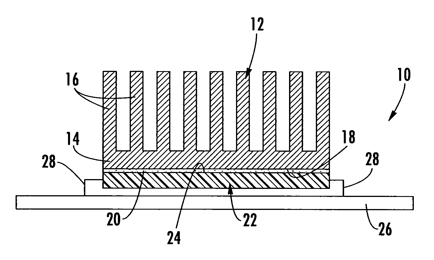
[0026]Referring now to the drawings, the heat dissipation assembly of the present invention is shown and illustrated generally as 10. The present invention is a heat dissipation assembly 10 and a method by which that assembly, formed by combining an elastomeric polymer base matrix and a thermally conductive filler, is molded into a finished component for final installation onto a heat generating electronic device.

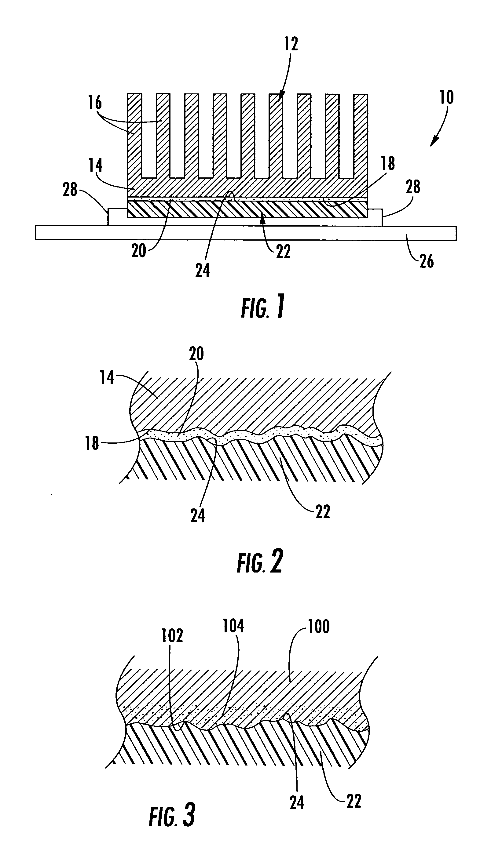
[0027]The assembly 10 of the present invention is shown here, by way of example, as a heat sink device 12 having a base element 14, integrally formed surface area enhancements 16 and an interface surface 18 to which an adhesive layer 20 is applied. The heat sink device 12 is applied to a heat generating electronic device 22 that has a heat generating surface 24 and is typically installed onto an electronic circuit board 26 via wire leads 28. While specific structure is used here to illustrate the present invention, it would be understood by one skilled in the relevant art ...


PUM

PropertyMeasurementUnit
Thicknessaaaaaaaaaa
Pressureaaaaaaaaaa
Flexibilityaaaaaaaaaa

Abstract

The present invention discloses a net-shape molded elastomeric heat-dissipating device that includes an integrally formed conformable interface surface. A base elastomeric matrix material is loaded with thermally conductive filler and injected into a mold cavity to form the completed device. Further, a layer of thermally conductive pressure sensitive adhesive material is applied to the conformable interface surface to allow the device to be securely fastened to a heat-generating surface. The present invention provides superior sealing and elimination of voids and air gaps that are typically found between the thermal transfer surfaces thereby facilitating enhanced thermal transfer properties. In addition, the present invention provides a method of manufacturing an elastomeric heat sink device as described above.

Description

CROSS-REFERENCE TO RELATED APPLICATIONS[0001]This application is related to and claims priority from earlier filed provisional patent application Nos. 60 / 314,433 filed Aug. 23, 2001 and 60 / 314,892 filed Aug. 24, 2001.BACKGROUND OF THE INVENTION[0002]The present invention relates generally to an elastomeric material composition for use in connection with heat generating electronic devices and a method for manufacturing the same. More particularly, this invention relates to a new net-shape molded thermally conductive elastomeric polymer heat sink device having an integral interface and fastening means. The composition contains thermally conductive filler material in a conformable elastomeric matrix and an integral means for adhering the device to a heat-generating surface to forming an improved heat sink device with an integral, conformable thermally conductive interface layer. Further, a method of manufacturing the device is also provided.[0003]In the prior art, it is well known that...

Claims


Application Information

Patent Timeline
IPC IPC(8): F28F3/00F28F3/02
CPCF28F3/02F28F3/022Y10T29/4935
Inventor SAGAL, E. MIKHAILPANEK, JEFFREYMCCULLOUGH, KEVIN A.
Owner TICONA POLYMERS INC
Why Eureka
Try Eureka