
Surgical instrument with integral optical system

a surgical instrument and optical system technology, applied in the field of surgical instruments, can solve the problems of severe constraints on the space available for the placement of surgical instruments, the reduction of the incision size to the incision depth ratio, and the limited visualization of the surgical area, so as to achieve the effect of reducing shadowing and visual obstruction

Inactive Publication Date: 2006-09-21
LIEPONIS JONAS V
View PDF17 Cites 66 Cited by
  • Summary
  • Abstract
  • Description
  • Claims
  • Application Information

AI Technical Summary

Benefits of technology

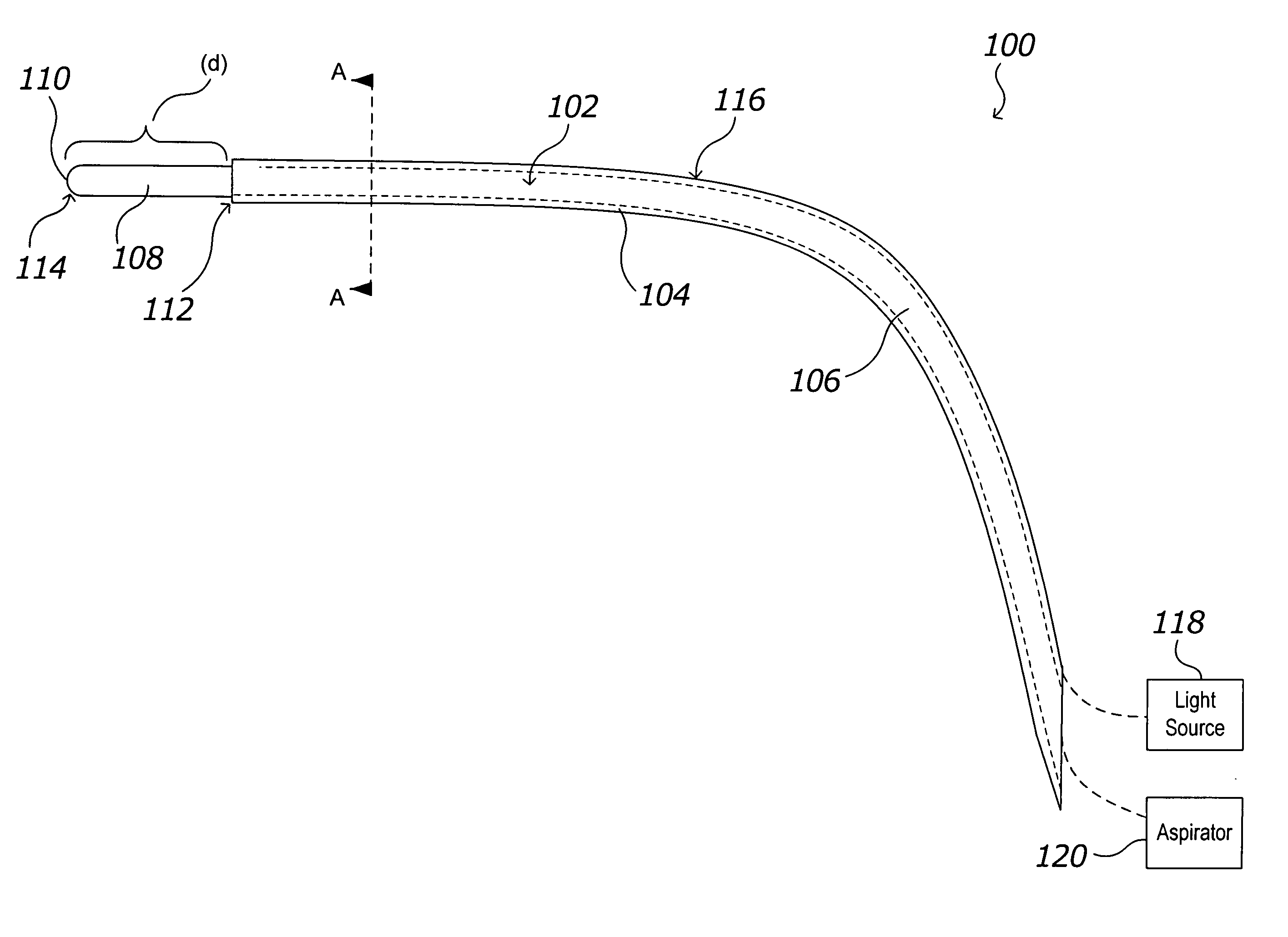
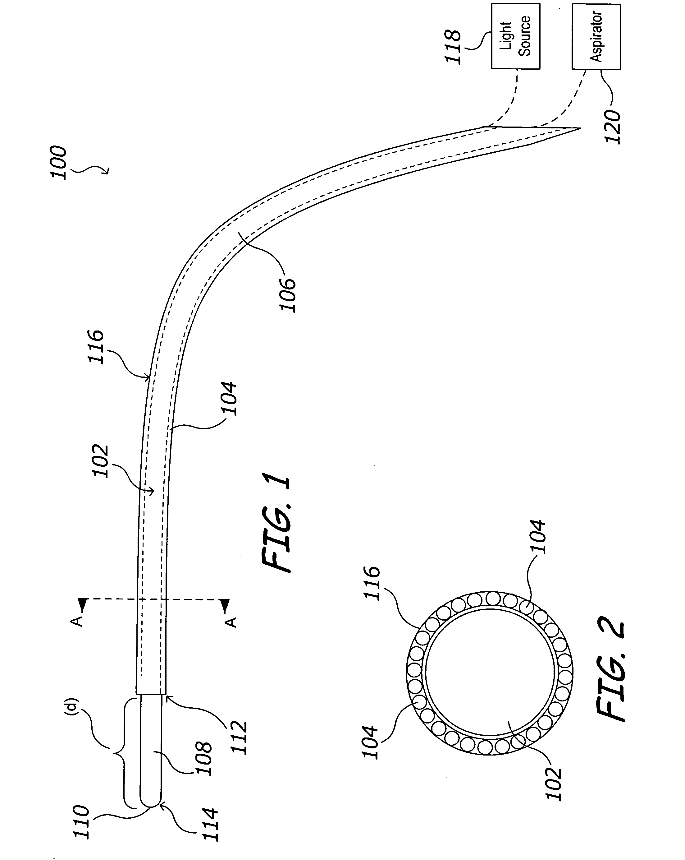
[0013] These and other objectives are achieved by provision of a surgical device that combines the applications of visualization and suction into a single instrument. Illuminating light is transmitted down the length of the device by means of optical fibers, which are concentrically positioned around an aspiration tube. The optical fibers are terminated at a distance from the tip of the device, which is provided as a transparent or translucent material to minimize shadowing and visual obstruction.

Problems solved by technology

Therefore, the incision size to incision depth ratio has been markedly decreased very often geometrically creating unique challenges for the surgeon.
For example, unique geometry of the reduced size of the incision places severe constraints on the space available for the placement of surgical instruments in the area where the procedure is being performed.
Visualization of the surgical area is also severely limited due to among other things, the size of the incision.
As such, the size and number of surgical instruments that may be simultaneously used during minimally invasive surgical procedures is quite limited.
The proximity of the suction and visualization devices creates additional challenges relating to: design and material choice, and cost of manufacture / purchase.
With relatively tight space constraints, this type of cutting tool may frequently come into contact with other surgical devices positioned within the surgical area.
It is not uncommon for the other surgical devices to become damaged by this incidental contact.
This can become quite costly for the hospital / surgeon to have to regularly repair and / or replace expensive surgical equipment in this manner.
A number of previous systems have attempted to address a few of these problems with limited success.
However, Dandolu fails to teach or suggest a system that focuses illuminating light ahead of the suction tip.
Additionally, Dandolu is described as comprising stainless steel, which is undesirable because in tight operating environments, when a relatively high-speed abrasive rotating instrument comes into contact with surgical tools, particles can be produced, which cannot subsequently be removed from the surgical area.
This is especially undesirable if the particles are metallic (e.g. stainless steel) because they may produce artifacts on post-operative imaging studies.
However, Issalene et al. again fails to teach or suggest a system that focuses illuminating light at a point ahead of the suction tip.
Issalene et al. also fails to teach use of optical fibers, but rather uses the wall of the cannula itself to transmit the illuminating light.
This may provide enough illuminating light for dental procedures, but would not be adequate, for example, for a minimally invasive surgical procedure.
However, Uram positions the illuminating / image guides and aspiration tube side-by-side, which disadvantageously increases the overall size of the device.
Accordingly, Uram fails to teach a combination suction and illumination device that presents one concentric system to provide the smallest diameter possible.
In addition, as the illumination guide is offset from the suction tube, Uram also fails to teach or suggest a system that focuses illuminating light at a point ahead of the suction tip.

Method used


Image

  • Surgical instrument with integral optical system
  • Surgical instrument with integral optical system
  • Surgical instrument with integral optical system

Examples


Embodiment Construction

[0038] Referring now to the drawings, wherein like reference numerals designate corresponding structure throughout the views.

[0039]FIG. 1 depicts aspiration and illumination device 100 according to one advantageous aspect of the present invention. Aspiration and illumination device 100 generally comprises aspiration conduit 102 and optical fibers 104. As illustrated in FIG. 2 along section line AA, optical fibers 104 are positioned circumferentially about aspiration conduit 102.

[0040] Aspiration conduit 102, in one advantageous embodiment, preferably comprises a non-metallic substance such as, for example, a flexible plastic material. It is further contemplated that aspiration conduit 102 may be provided of a material that can hold a shape when deformed providing increased control for the surgeon.

[0041] As can be seen in FIG. 1, aspiration conduit 102 comprises a body portion 106 and a tip 108, the tip 108 provided with a distal end 110. In one advantageous embodiment, tip 108 is...


PUM


Abstract

A combination aspiration and illumination device using optical fibers circumferentially disposed around the aspiration conduit for transmitting illuminating light to a cavity to be aspirated. The ends of the optical fibers being formed at an angle relative to the aspiration conduit so as to direct the illuminating light inward to provide intensified illumination ahead of the aspiration conduit.

Description

CROSS-REFERENCE TO RELATED APPLICATIONS [0001] This applicaiton claims the benefit of the filing date of U.S. Patent Application Ser. No. 60 / 663,690 filed Mar. 21, 2005.FIELD OF THE INVENTION [0002] This invention relates to a surgical instrument, more specifically this invention relates to a combination suction device and optical device that may provide a visual indication of the area in which the tool is inserted. BACKGROUND OF THE INVENTION [0003] Minimally invasive surgery provides some significant advantages over open surgical procedures and as such, is being more frequently utilized. However, minimally invasive surgery and surgical techniques, for example, minimal incision surgery such as is utilized in spinal procedures, have created a special set of requirements with regard to the visualization of the operative field. These special requirements or changed parameters include the operative field being significantly reduced in size as compared to open surgical procedures. Howev...

Claims


Application Information

Patent Timeline
Patent Type & Authority Applications(United States)
IPC IPC(8): A61B1/06A61B1/12
CPCA61B1/00165A61B2019/5206A61M1/008A61B1/0607A61B1/07A61B2090/306A61M1/84
Inventor LIEPONIS, JONAS V.
Owner LIEPONIS JONAS V
Learn More