
Eureka
For R&D, Eureka makes reading and utilizing patents & technical documents easy.
Eureka AIR
Designed for self-driven R&D workflows. Generate viable solutions, solve complex R&D challenges, empower your innovation with AI.

Eureka Materials
Designed for material experts only. Revolutionize your material R&D, from search, analyze, to developing new materials.

TechResearch
Generate reliable direction feasibility study reports for your R&D in just a few steps.

TechSeek
Discover and master advanced knowledge NOW. Basics, ideas, possibilities, all at once.

TechMind
As an expert in R&D Theories, TechMind can generates customized viable solutions instantly.

TechRisk
Analyze your overall solution with one click, know your potential R&D risks in advance.

TechMonitor
Get weekly tech updates, stay abreast of the latest tech innovations and key insights.
Ice making machine
- Summary
- Abstract
- Description
- Claims
- Application Information
AI Technical Summary
Benefits of technology
Problems solved by technology
Method used
Image

Examples
embodiment 1
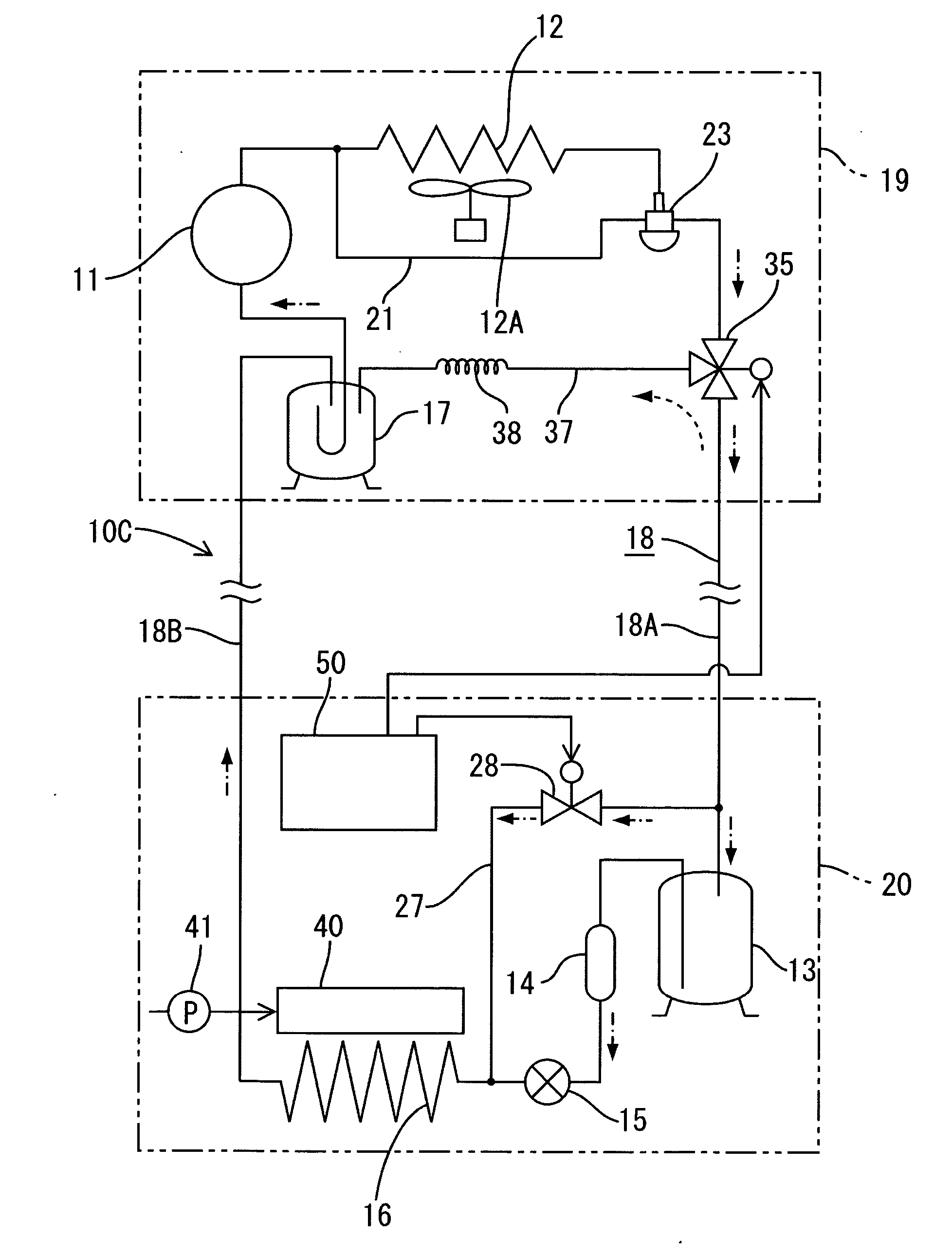
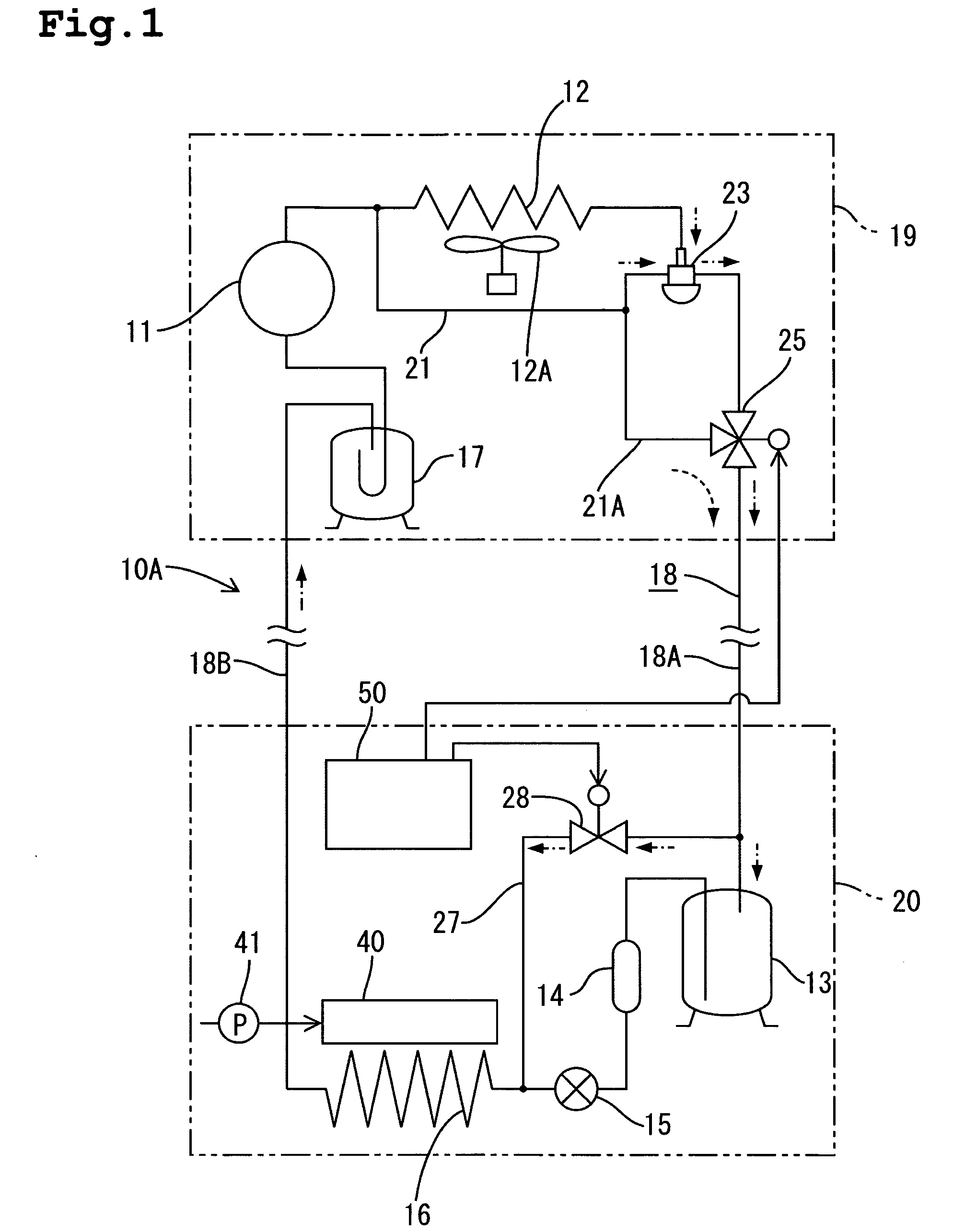
[0022] Embodiment 1 of this invention is described hereafter referring to FIG. 1 and FIG. 2. In a cooling system 10A of Embodiment 1, a compressor 11, a condenser 12 with a condenser fan 12A, a receiver 13, a dryer 14, an expansion valve 15, an evaporator 16, and an accumulator 17 (i.e., liquid separator), are connected in a circulatory manner by refrigerant piping 18 that includes a refrigerant supply line 18A and a refrigerant return line 18B. Of these components, the compressor 11, condenser 12, and accumulator 17, are disposed in an external unit 19, and the remaining components are disposed in an internal unit 20. On the outlet side of the condenser 12 a condensing pressure regulating valve 23 (CPR) is disposed at a position between the condenser 12 and the receiver 13. The condensing pressure regulating valve 23 has two inlets and one outlet. One of the inlets is connected with an outlet of the condenser 12. The other inlet is connected to a first bypass line 21 that leads fro...
embodiment 2
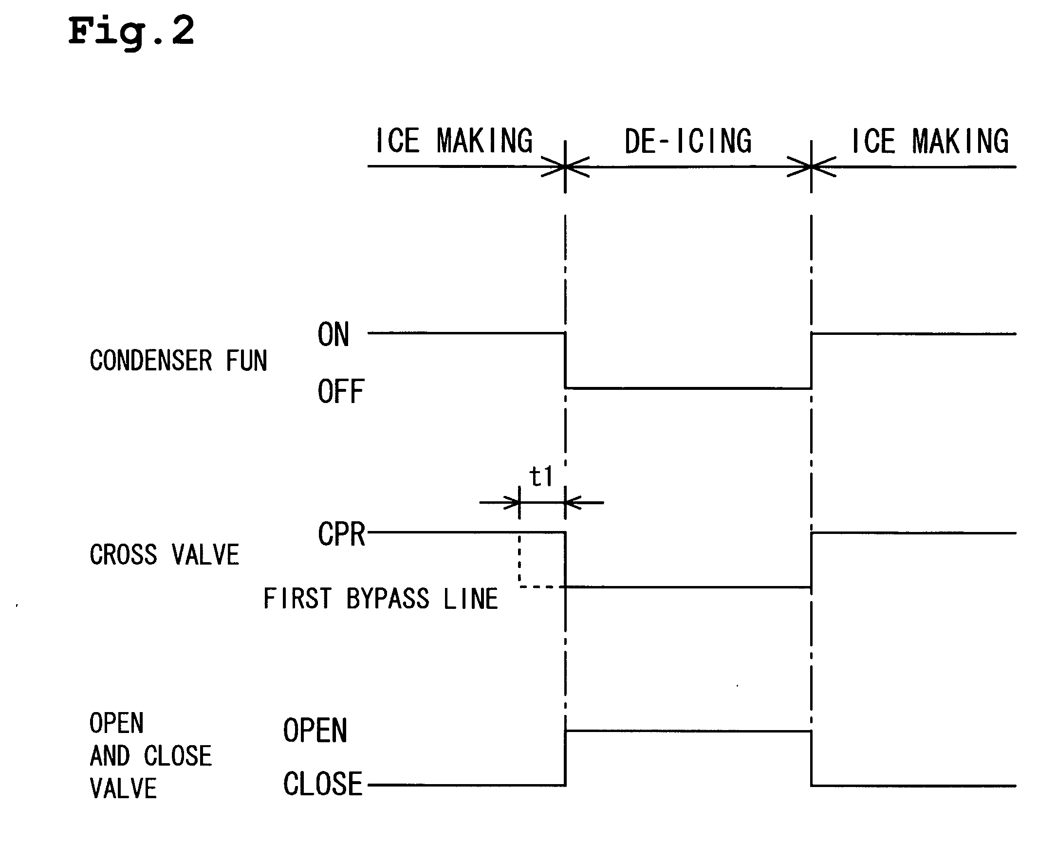
[0032] In Embodiment 2, when switching to a de-icing operation, a time difference is implemented between switching of the three-way valve 25 to the side of the first bypass line 21 and opening of the open / close valve 28. More specifically, as shown by the dashed line in the above-described FIG. 2, after the three-way valve 25 switches to the side of the first bypass line 21, the open / close valve 28 is opened after the lapse of a predetermined delay time ti (e.g., from several tens of seconds to about two minutes). The predetermined delay time t1 is measured utilizing a timer. This means that hot gas is first allowed to flow into the refrigerant supply line 18A to collect the liquid refrigerant within the line 18A in the receiver 13. Thereafter, the open / close valve 28 is opened. Thus, since only hot gas is introduced into the evaporator 16 in the de-icing operation without introducing liquid refrigerant therein, when the liquid refrigerant inside the refrigerant supply line 18A is o...
embodiment 3
[0033] In this embodiment, the above Embodiment 2 is further developed. While there is a general tendency to consider it disadvantageous for a de-icing operation to introduce the liquid refrigerant remaining in the refrigerant supply line 18A into the evaporator 16 when commencing a de-icing operation, it has been confirmed that, on the contrary, when the temperature of that liquid refrigerant is high the de-icing performance is enhanced. This is thought to be due to the superior heat transfer properties of liquid as compared to those of gas. Alternatively however, when the temperature of the liquid refrigerant is low the liquid refrigerant results in a weakening of the effect of the hot gas.
[0034] Therefore, a temperature sensor (not shown in the figure) is provided that detects the ambient temperature of the external unit 19 to thereby detect the temperature of the liquid refrigerant remaining inside the refrigerant supply line 18A through condensation. Thus, as shown in FIG. 3, ...
PUM
 Abstract
Description
Claims
Application Information
 - R&D Engineer
- R&D Manager
- IP Professional
- Industry Leading Data Capabilities
- Powerful AI technology
- Patent DNA Extraction
Browse by: Latest US Patents, China's latest patents, Technical Efficacy Thesaurus, Application Domain, Technology Topic, Popular Technical Reports.
© 2024 PatSnap. All rights reserved.Legal|Privacy policy|Modern Slavery Act Transparency Statement|Sitemap|About US| Contact US: help@patsnap.com