Compact, modular method and apparatus for liquefying natural gas

a natural gas and modular technology, applied in the field of cryogenic refrigeration cycles, can solve the problems of complicated dispersion of gas, high cost and maintenance costs of such plants, and the inability to produce liquid from methane with high pressure alon

Inactive Publication Date: 2006-09-28
CAMBRIDGE CRYOGENICS TECH
View PDF34 Cites 76 Cited by
  • Summary
  • Abstract
  • Description
  • Claims
  • Application Information

AI Technical Summary

Benefits of technology

[0016] Accordingly, the present invention relates to a compact and modular method and apparatus for the liquefaction of gas, typically methane gas, in a single, highly efficient step involving no external or separate refrigeration system. The apparatus is environmentally safe, compact, and modular, such that it is cost-efficient to move the entire apparatus from one location to another in several days' time.

Problems solved by technology

However, producing liquid from methane may not be achieved with high pressure alone.
Unfortunately, the cost and maintenance of such plants is expensive because of the cost of constructing, operating and maintaining one or more external, single or mixed refrigerant, closed-loop cooling circuits.
Such circuits typically require the use and storage of multiple highly explosive refrigerants that can present safety concerns.
Refrigerants such as propane, ethylene and propylene are explosive, while propane and propylene, in particular, are heavier than air, further complicating dispersion of these gases in the event of a leak or other equipment failure.
The equipment used to liquefy cryogenic gases in high volumes is large, complex and very expensive.
Materials required in conventional liquefaction plants also contribute greatly to the plants' cost.
Another distinguishing feature of a conventional liquefaction plant in the prior art is that as a result of its complexity and size, the plant, by necessity, is typically a fixed installation that can not be easily relocated.
Even if a conventional plant can be physically relocated, such a move is very costly and requires the plant to be out of service for many months while plant systems, components and structures are disassembled, moved and then reassembled on a newly prepared site.
While the Engel process produces LNG without the use of external refrigerants, the process yields a small volume of LNG compared to the amount of work required for its production, thus limiting the economic viability of the process.

Method used


Image

  • Compact, modular method and apparatus for liquefying natural gas
  • Compact, modular method and apparatus for liquefying natural gas
  • Compact, modular method and apparatus for liquefying natural gas

Examples


case 2b

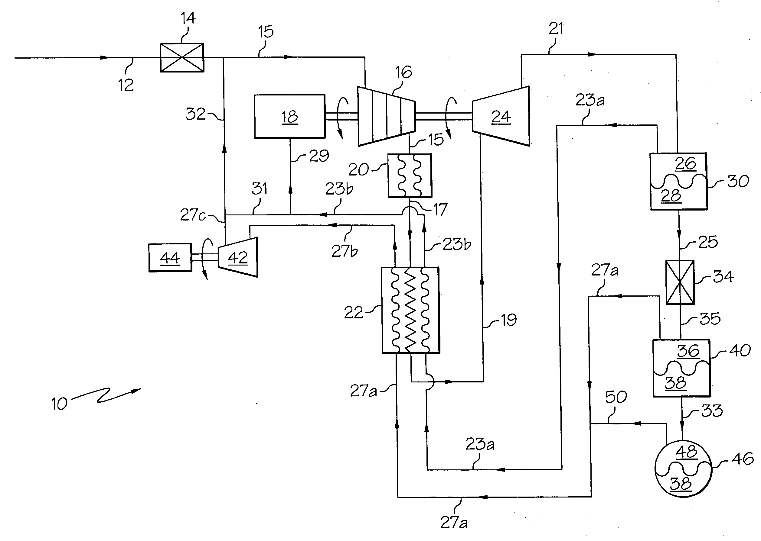
[0057] Case 2b of TABLE 1 summarizes typical cycle conditions using a typical “pipeline quality” natural gas as the feed gas, consisting of 98.00% methane gas, 0.75% ethane, 0.50% propane, 0.20% normal butane, 0.25% nitrogen and 0.30% carbon dioxide. Case 2c of TABLE 1 summarizes typical cycle conditions using a representative field gas that is rich in carbon dioxide as the feed gas, consisting of 88.00% methane, 0.75% ethane, 0.50% propane, 0.20% normal butane, 0.25% nitrogen, and 10.30% carbon dioxide. Case 2d summarizes typical cycle conditions using a representative field gas that is also rich in nitrogen as the feed gas, consisting of 88.00% methane, 0.75% ethane, 0.50% propane, 0.20% normal butane, 10.25% nitrogen, and 0.30% carbon dioxide.

TABLE 1CompressorExpanderLNGDischargeInletExpander DischargeThrottle Valve OutletProductionPressTFlowPressTPressTempVaporLiquidPressTempVaporLiquidLiquidPower OutputCasepsia° F.mmscfdpsia° F.psia° F.%%psia° F.%%%Hp12994.7803.5702964.7−29.012...


PUM


Abstract

A compact and modular cryogenic method and apparatus for liquefying natural gas. The liquefaction process is highly efficient and requires no external refrigeration system, and the apparatus is small enough to be transportable from one remote site to another. A compressed natural gas feed stream is cooled and then expanded to form a bi-phase stream comprising a first refrigerated vapor component and a first liquid component. The first liquid component is then separated from the bi-phase stream and expanded to form a second bi-phase stream comprising a second refrigerated vapor component and a second liquid component. The second liquid component is then introduced into a means configured for storage and transport. The remaining feed stream can then be recycled, and at least a substantial portion of the original feed stream can be processed into liquefied natural gas (LNG). The first and second vapor components are recycled through the system and comprise at least a portion of the feed stream in the repeated steps.

Description

CROSS-REFERENCE TO RELATED APPLICATION [0001] This application claims the benefit of U.S. Provisional Application No. 60 / 665,666, filed on Mar. 28, 2005.FIELD OF THE INVENTION [0002] The present invention relates in general to cryogenic refrigeration cycles useful in many commercial and industrial applications including the liquefaction of gases. BACKGROUND OF THE INVENTION [0003] There are numerous reasons for the liquefaction of gases, including naturally occurring gases such as methane. Perhaps the chief reason is that liquefaction greatly reduces the volume of a gas, making it feasible to store and transport the liquefied gas in containers of improved economy and design. Liquid gases can be stored in suitably designed cryogenic containers and dispensed into vehicle tanks using techniques that have been in use for many years in the industrial cryogenic gas industries. [0004] Many industrial gases such as propane, butane and carbon dioxide can be liquefied by placing them under ve...

Claims


Application Information

Patent Timeline
Patent Type & Authority Applications(United States)
IPC IPC(8): F25J1/00
CPCF25J1/0202F25J1/0283F25J1/0287F25J2205/02F25J2220/62F25J2230/60F25J2240/02F25J1/0022F25J1/0035F25J1/004F25J1/0232F25J1/0257F25J1/0258F25J1/0259F25J1/0275F25J1/0042F25J2240/30F25J1/001F25J1/0017F25J1/002F25J1/0027F25J1/005F25J1/0052F25J1/0082F25J1/0265F25J1/0288F25J2230/20F25J1/0254F25J2240/40
Inventor WHITESELL, ROBERT
Owner CAMBRIDGE CRYOGENICS TECH
Why Eureka
Try Eureka