
Slip joint assembly with coated splines and method

a technology of coating splines and joints, applied in the direction of couplings, manufacturing tools, other domestic articles, etc., can solve the problems of slip joint wear, slip joint difficulty in decoupling, cost and complexity of slip joint assembly,

Active Publication Date: 2006-09-28
AMERICAN AXLE & MFG
View PDF27 Cites 14 Cited by
  • Summary
  • Abstract
  • Description
  • Claims
  • Application Information

AI Technical Summary

Problems solved by technology

In a loaded condition, the slip joint can be difficult to decouple.
In the loaded condition, however, the slip joint can experience wear due to heat generation.
The additional machining and / or handling of the injection of the plastic can add cost and complexity to slip joint assembly.

Method used


Image

  • Slip joint assembly with coated splines and method
  • Slip joint assembly with coated splines and method
  • Slip joint assembly with coated splines and method

Examples


Embodiment Construction

[0014] The following description of the various embodiments is merely exemplary in nature and is in no way intended to limit the invention, its application, or uses.

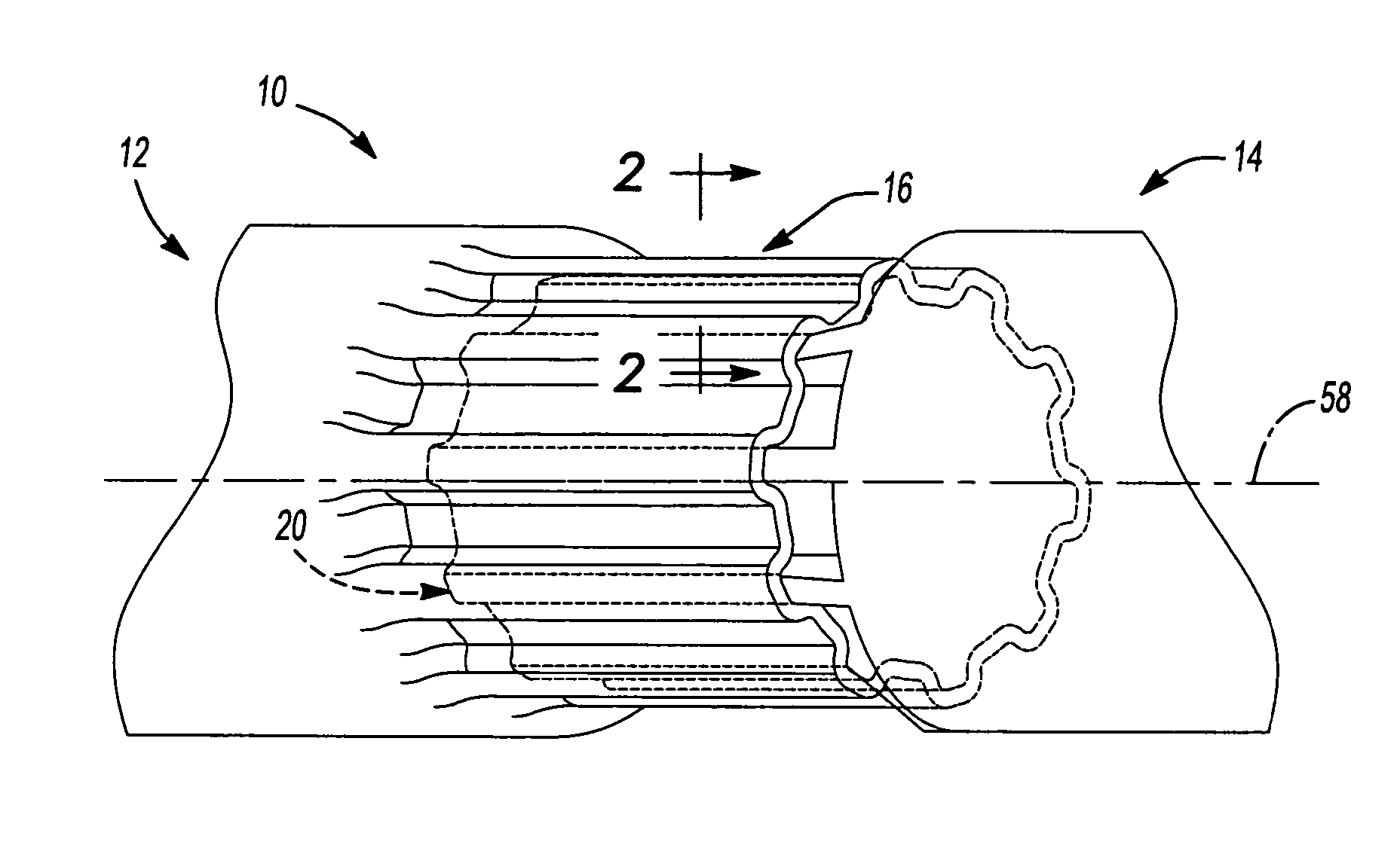
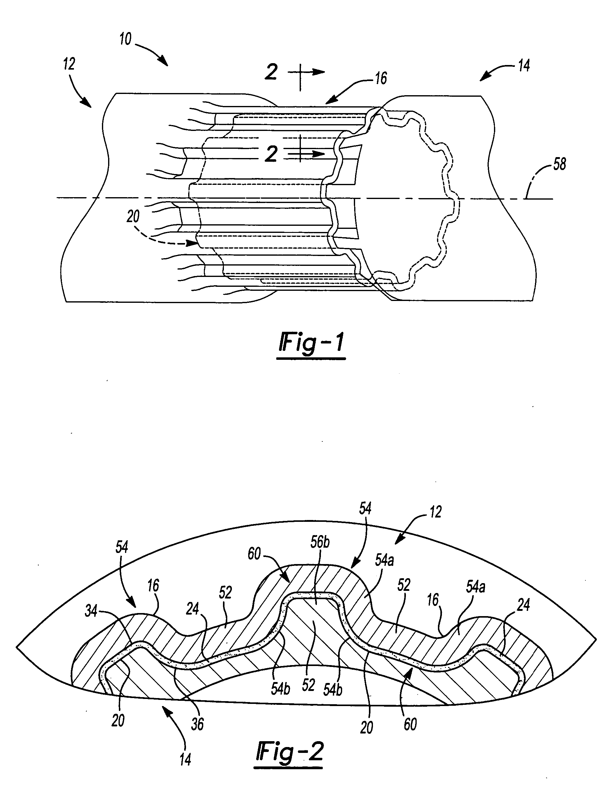
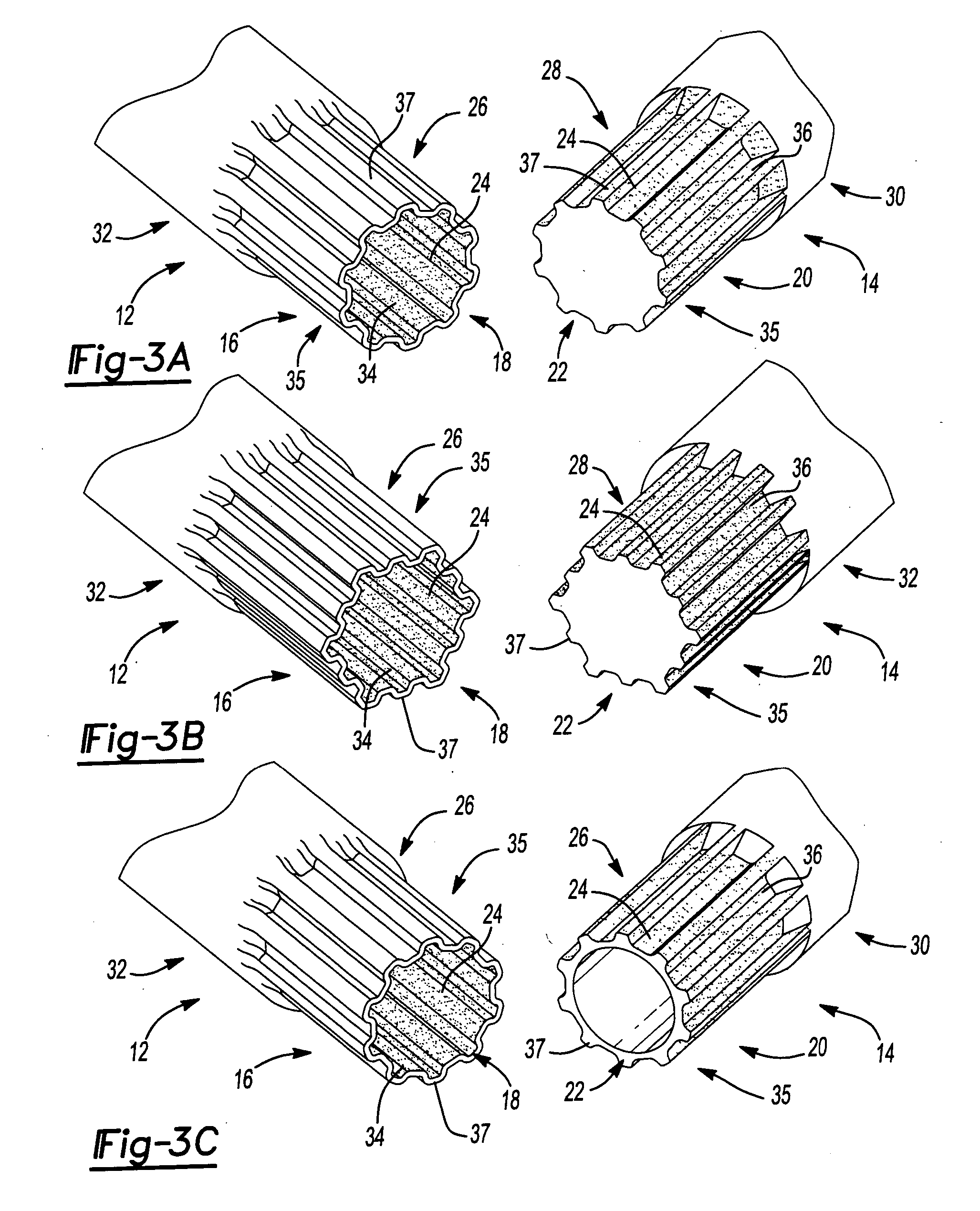
[0015] With reference to FIGS. 1 and 2, a slip joint 10 is shown that is constructed in accordance with the teachings of the present invention. The slip joint 10 can include a female member 12 that can be coupled to a male member 14. With reference to FIGS. 3A, 3B and 3C, additional members 12, 14 that can form the slip joint 10 are shown. The female members 12 can have female splines 16 formed on a female end 18 of the female member 12. The male members 14 can have male splines 20 formed on a male end 22 of each of the male members 14. Each of the male ends 22 can be configured to be received by each of the female ends 18 of the female members 12. It will be appreciated that the terms male and female are used only so much as to indicate that one member can be received in the other (i.e., a male member into a female mem...


PUM

PropertyMeasurementUnit
thicknessaaaaaaaaaa
polymericaaaaaaaaaa
diameteraaaaaaaaaa

Abstract

A method includes providing a shaft having a coupling section. The coupling section has a generally cylindrical exterior surface. The method includes applying a coating to the coupling section to form an engaging surface. The method further includes cold-forming the shaft and the coating such that a plurality of protrusions is formed in the engaging surface. The cold-forming of the shaft and the coating is performed contemporaneously.

Description

FIELD OF THE INVENTION [0001] The present invention relates to a slip joint assembly and more particularly to forming of coated splines. BACKGROUND OF THE INVENTION [0002] A traditional slip joint can connect two members together. In one example, male splines formed on one member can be slipped into female splines formed on the other member. The splines can be formed by myriad processes that can include cold-forming. Various types of cold-forming processes are commonly referred to as Grob cold-rolling processes or Grobing. Briefly, the Grob processes include forming splines, gear teeth etc. on a tube, shaft or rod by, for example, inserting a mandrel into the member and hammer-forming the member against the mandrel to form a spline end. Other Grobing processes can include cold-rolling and vibration forming. [0003] In an unloaded condition, the members of the slip joint can more longitudinally relative to one another. In a loaded condition, the slip joint can be difficult to decouple...

Claims


Application Information

Patent Timeline
Patent Type & Authority Applications(United States)
IPC IPC(8): B21D41/00
CPCB21D15/02B21D53/28B21H7/187F16C3/03F16D3/06B23P15/00
Inventor BRISSETTE, RONALD N.
Owner AMERICAN AXLE & MFG
Learn More