NMR methods for measuring fluid flow rates

a technology of fluid flow rate and nuclear magnetic resonance, which is applied in the direction of nmr measurement, reradiation, instruments, etc., can solve the problems of affecting the flow, complicating the installation of the measuring device into the existing fluid system, and exposing the measuring device to potentially harmful fluids. , to achieve the effect of reducing the cost of measuremen

Inactive Publication Date: 2006-09-28
ROLLS ROYCE PLC
View PDF7 Cites 16 Cited by
  • Summary
  • Abstract
  • Description
  • Claims
  • Application Information

AI Technical Summary

Benefits of technology

[0064] This preferred approach gives a low resolution output, the effect of which is that the series of peaks seen in a high resolution frequency spectrum merge to form a single peak or resonance.
[0065] It may be thought that this loss of resolution would be disadvantageous, because a degree of information is lost from the NMR signal. However, as explained in EP 1191330, this low resolution approach can provide useful results and has the significant advantage that subsequent analysis is greatly simplified. The possibility it provides for using much less powerful, and hence much smaller magnets than conventional techniques is also a significant advantage.

Problems solved by technology

This can undesirably affect the flow, expose the measuring device to possibly harmful fluids, and complicate installation of measuring devices into existing fluid systems.
However, the gradient coil requires additional (generally heavy and expensive) field gradient amplifiers and control circuits, and the time of flight approach requires a separate detector coil and is limited by the relaxation time of the fluid.
The approach is possible where the particulates have a different magnetic susceptibility than the fluid, because they will then cause local non-uniformities in the magnetic field.

Method used


Image

  • NMR methods for measuring fluid flow rates
  • NMR methods for measuring fluid flow rates
  • NMR methods for measuring fluid flow rates

Examples


Embodiment Construction

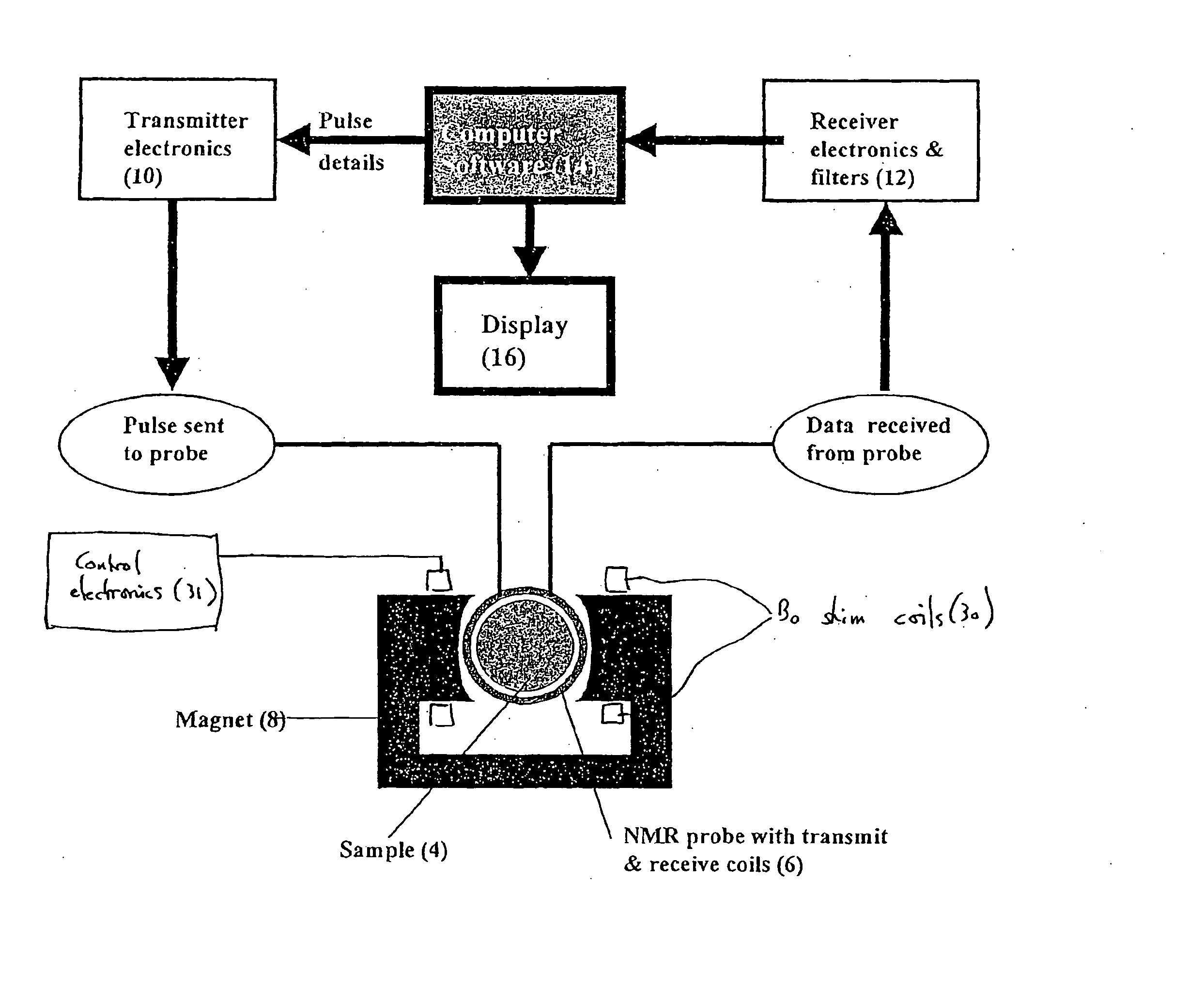
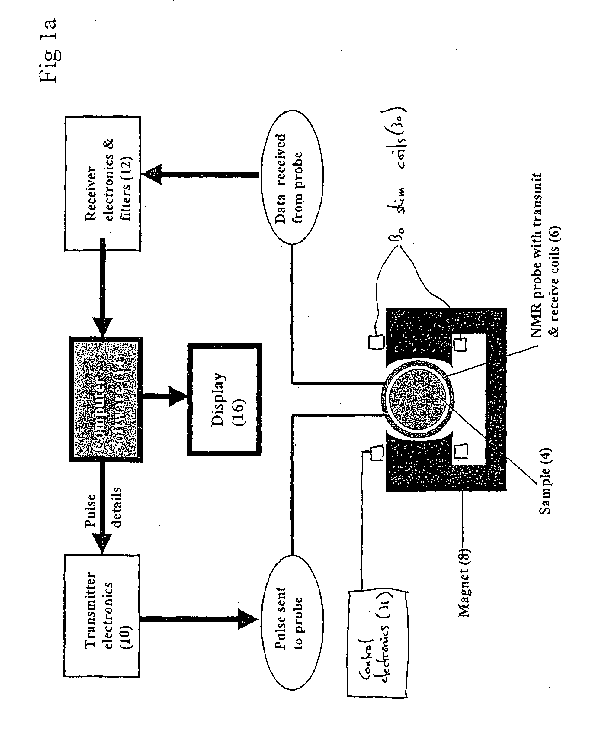
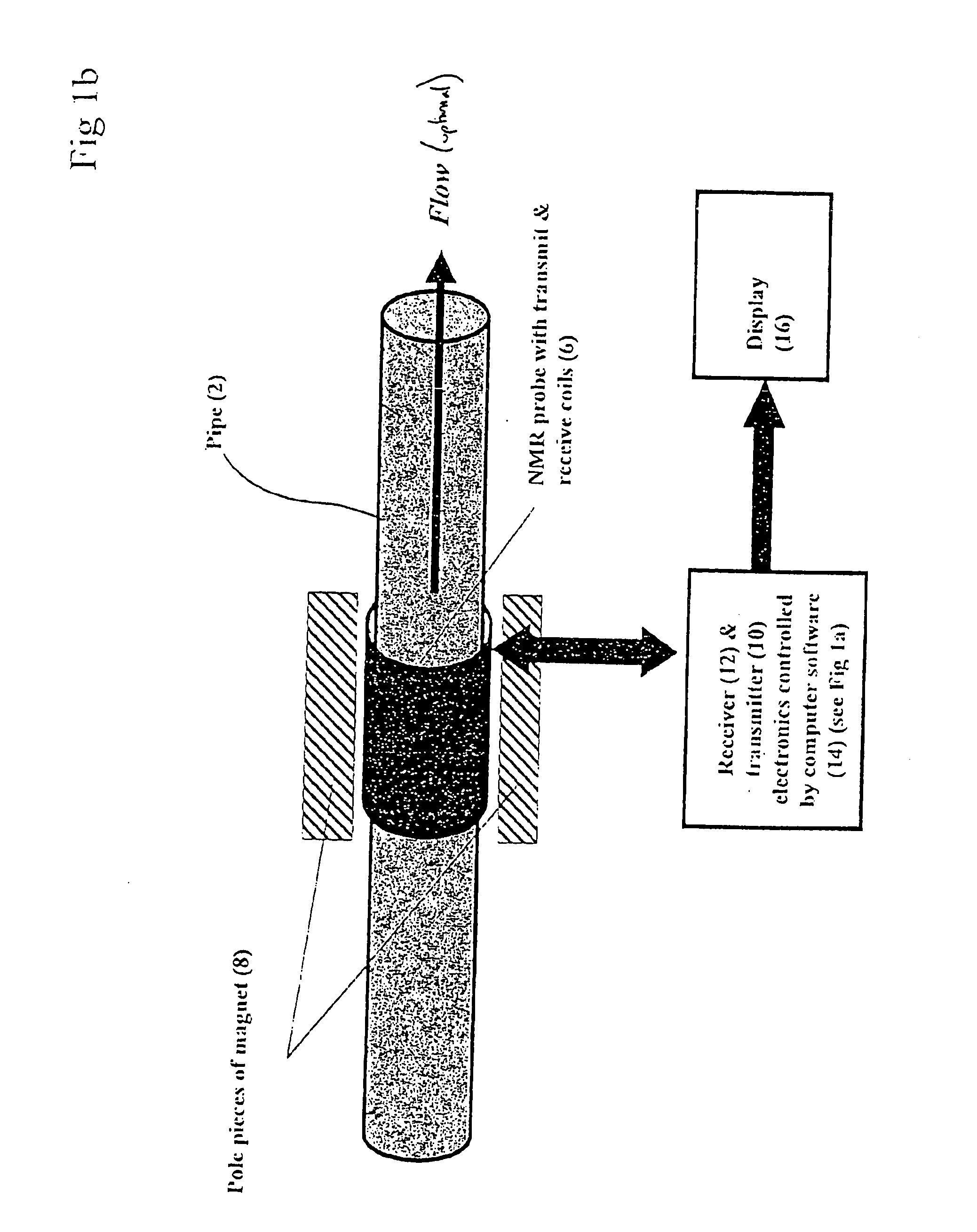
[0074] Methods according to various aspects of the invention will be exemplified by way of a test which has been implemented using a 10.81 MHz bench-top NMR spectrometer. The system is illustrated schematically in FIGS. 1 and 2. Some implementations have been tested with a similar NMR spectrometer with a 0.066 T magnet (2.28 MHz).

[0075] Looking at the system as a whole, the main components are a non-ferromagnetic sample pipe 2, within which a liquid sample to be evaluated flows, an annular probe head 6 that surrounds the sample pipe 2, and hence the sample 4 itself, and a magnet 8 which partially surrounds the probe head 6, and current-carrying B0 shim coils 30.

[0076] The magnet 8 provides a fixed strength, non-oscillating magnetic field, and B0 shim coils 30 are arranged to produce a B0 shim field which is parallel to and superimposed upon this non-oscillating field. The B0 shim field is in the same or opposite direction to the main static field generated by magnet 8 and allows t...


PUM


Abstract

A method for measuring fluid flow rates comprises the steps of: (a) creating a non-oscillating magnetic field of a predetermined strength across a flowing fluid; (b) performing the sub-steps of: (i) exposing the flowing fluid to an oscillating magnetic field pulse orthogonal to the non-oscillating magnetic field to generate an NMR signal, and (ii) detecting the NMR signal from the flowing fluid in the form of a free induction decay; and (c) determining the fluid flow rate from the initial magnitude of the free induction decay.

Description

FIELD OF THE INVENTION [0001] This invention is generally concerned with Nuclear Magnetic Resonance (NMR) methods for measuring fluid flow rates. In particular, although not necessarily exclusively, the fluid may be oil (e.g. engine lubricating or cooling oil), fuel, coolants (e.g. water) or hydraulic fluid in a power plant or other machinery. BACKGROUND [0002] Accurate flow measurement is increasingly important in many fields. For example, in the field of civil aircraft, increases in accuracy in the flow measuring systems used to meter fuel mean that less fuel has to be carried by aircraft to compensate for measuring inaccuracies, which in turn leads to improvements in fuel consumption. [0003] Most mechanical fluid flow measuring devices intrude to some extent into the flow they are set up to measure. This can undesirably affect the flow, expose the measuring device to possibly harmful fluids, and complicate installation of measuring devices into existing fluid systems. [0004] In v...

Claims


Application Information

Patent Timeline
Patent Type & Authority Applications(United States)
IPC IPC(8): G01F1/58G01F1/716G01R33/44G01R33/563
CPCG01R33/44G01R33/563G01F1/716
Inventor MORRIS, PETER G.MOORE, TERRYANUZIS, PAULASTLEY, KENNETH
Owner ROLLS ROYCE PLC
Why Eureka
Try Eureka