Wear resistant cutting blade

a cutting blade and wear-resistant technology, applied in the field of cutting blades, can solve the problems of blade wear generally beginning from the tip of the trailing edge inward, blade will likely be replaced, cutting edge dulling, etc., and achieve the effect of not prematurely weakened blade parts

Inactive Publication Date: 2006-09-28
FISHER BARTON
View PDF21 Cites 22 Cited by
  • Summary
  • Abstract
  • Description
  • Claims
  • Application Information

AI Technical Summary

Benefits of technology

[0008] The wear-resistant characteristic, material, or treatment is selectively placed or applied largely, or perhaps only, in the radiused portions of the blade, instead of over the entire working portions of the blade, as has been previously done. In other embodiments, the wear-resistant characteristic, material, or treatment is applied in greater measure to the radiused portions of the blade than to adjacent portions of the blade. In either case, the radiused portions of the blade are therefore made to be more wear-resistant relative to at least the trailing edge of the blade. A more natural and desirable wear pattern from the outer-most tip of the bent portions of the blade inward is achieved. More importantly, the bent portions of the blade will not be prematurely weakened due to early undercutting wear in the radiused portions of the blade.

Problems solved by technology

Therefore, the blade will generally begin to wear from the tip of the trailing edge inward and the cutting edge will dull before any significant weakening of the material in the radiused portions will occur.
Thus, the blade will likely be replaced before the bend geometry is substantially changed to the detriment of cutting and airflow performance.

Method used


Image

  • Wear resistant cutting blade
  • Wear resistant cutting blade
  • Wear resistant cutting blade

Examples


Embodiment Construction

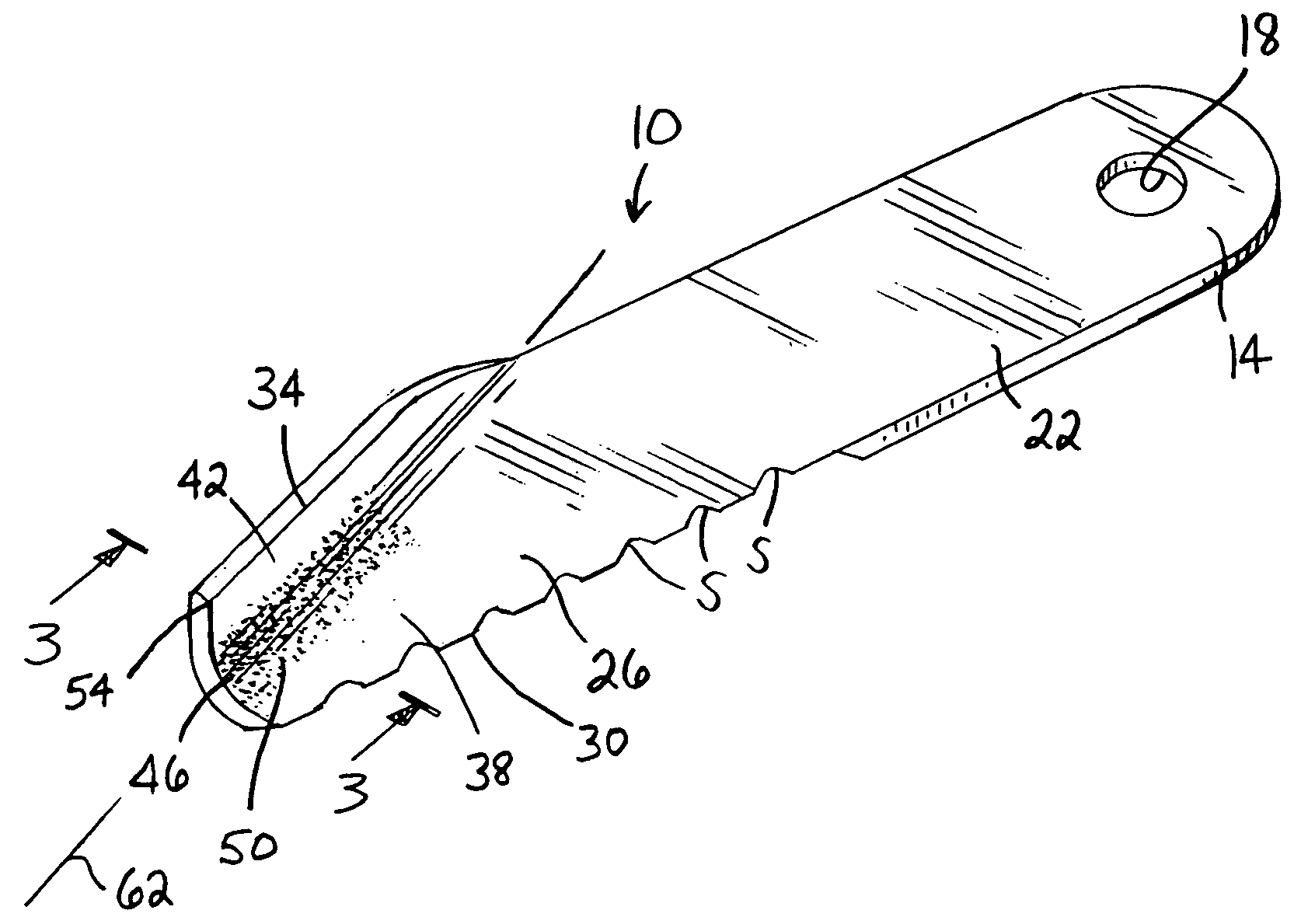
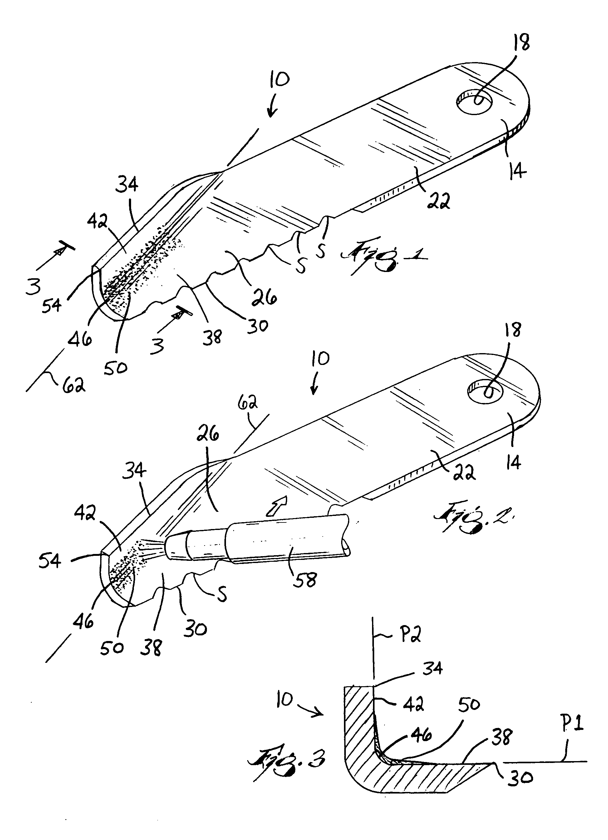
[0023]FIGS. 1-3 illustrate a blade 10 embodying the invention. The illustrated blade 10 is of the type commonly referred to as a straw chopping blade. However, as will be discussed in more detail below, the invention is not limited in application to straw chopping blades, but rather can be used with any style or type of cutting blade having one or more bent or otherwise formed portions that create radiused areas of high pressure and turbulence.

[0024] The blade 10 includes a mounting portion 14 having therein a mounting hole 18 for securing the blade 10 to a rotating member (not shown). A body portion 22 extends from the mounting portion 14 to a working portion 26. The blade 10 further includes a leading or cutting edge 30 and a trailing edge 34. In the illustrated embodiment, at least a portion of the cutting edge 30 is beveled and includes serrations S for improved cutting performance, however, different cutting edge configurations can also be used. For example, the cutting edge 3...


PUM

PropertyMeasurementUnit
angleaaaaaaaaaa
thicknessaaaaaaaaaa
depthaaaaaaaaaa

Abstract

A cutting blade includes a mounting portion and a working portion located at a distance from the mounting portion. The working portion includes a first surface portion at least partially lying in a first plane, a second surface portion at least partially lying in a second plane that is non-parallel to the first plane, and an intermediate surface portion between the first and second surface portions. At least part of the intermediate surface portion has a wear-resistant property that is substantially different from a wear-resistant property of at least part of the second surface portion. The intermediate surface portion can be treated via thermal spray coating, laser hardening, induction hardening, and other similar surface hardening processes. Additionally, a piece of hardened material can be bonded to the intermediate surface portion. Furthermore, the blade thickness adjacent the intermediate surface portion can be increased.

Description

FIELD OF THE INVENTION [0001] The invention relates to cutting blades used in agricultural applications, and more specifically to cutting blades having radiused portions created by a bend or formation in the blade material. BACKGROUND OF THE INVENTION [0002] Numerous types and configurations of cutting blades exist for various agricultural cutting and harvesting applications. A large number of these blades include radiused portions created by a bend or formation in the blade material. Often, a portion of the blade may be bent or formed to improve the cutting and air flow characteristics of the blade, as is the case in some mulching and shredding lawn mower blades. Additionally, the blade may be bent for other reasons, such as for increasing the air flow or fan action in the case of many straw chopping blades used in combines. [0003] The bends in the blade create high pressure areas in and near the radiused portions that are susceptible to wearing by the largely turbulent flowing edd...

Claims


Application Information

Patent Timeline
Patent Type & Authority Applications(United States)
IPC IPC(8): B26D1/00
CPCA01D34/005A01D34/73A01F29/09B26D1/0006B26D2001/002B26D2001/0053Y10T83/04
Inventor TURNER, DARREL L.WILKEY, RICHARD E.WILKEY, RICHARD L.
Owner FISHER BARTON
Why Eureka
Try Eureka